Method and System for Cooling a Hydrocarbon Stream Using a Gas Phase Refrigerant
Active Publication Date: 2019-10-31
AIR PROD & CHEM INC
View PDF0 Cites 0 Cited by
Summary
Abstract
Description
Claims
Application Information
AI Technical Summary
This helps you quickly interpret patents by identifying the three key elements:
Problems solved by technology
Method used
Benefits of technology
Benefits of technology
The patent describes methods and systems for liquefying natural gas using a refrigeration circuit with methane or methane and nitrogen. The system includes turbo-expanders and a J-T valve to provide efficient refrigeration for liquefying and sub-cooling the gas. The system uses a predominantly gaseous refrigerant, with a cold stream of vaporizing refrigerant at a lower pressure than the cold streams of gaseous refrigerant. These methods and systems produce an LNG product with high efficiency using available refrigerant, and the refrigerant remains in gaseous form throughout the refrigeration cycle.
Problems solved by technology
Designing and operating such a LNG plant on a floating platform poses, however, a number of challenges that need to be overcome.
Conventional liquefaction processes that use mixed refrigerant (MR) involve two-phase flow and separation of the liquid and vapor phases at certain points of the refrigeration cycle, which may lead to reduced performance due to liquid-vapor maldistribution if employed on a floating platform.
In addition, in any of the refrigeration cycles that employ a liquefied refrigerant, liquid sloshing may cause additional mechanical stresses.
However, the nitrogen recycle expander process has a relatively lower efficiency and involves larger heat exchangers, compressors, expanders and pipe sizes.
Nevertheless, there remains a need in the art for methods and systems for liquefying natural gas that utilize refrigeration cycles with high process efficiency that are suitable for use in FLNG applications, peak shaving facilities, and other scenarios where two-phase flow of refrigerant and separation of two-phase refrigerant is not preferred, maintenance of a large inventory of flammable refrigerant may be problematic, large quantiles of pure nitrogen or other required refrigerant components may be unavailable or difficult to obtain, and / or the available footprint for the plant places restrictions on the size of the heat exchangers, compressors, expanders and pipes that can be used in the refrigeration circuit.
Method used
Image
Click on the blue label to locate the original text in one second.
Reading with bidirectional positioning of images and text.
Examples
example 1
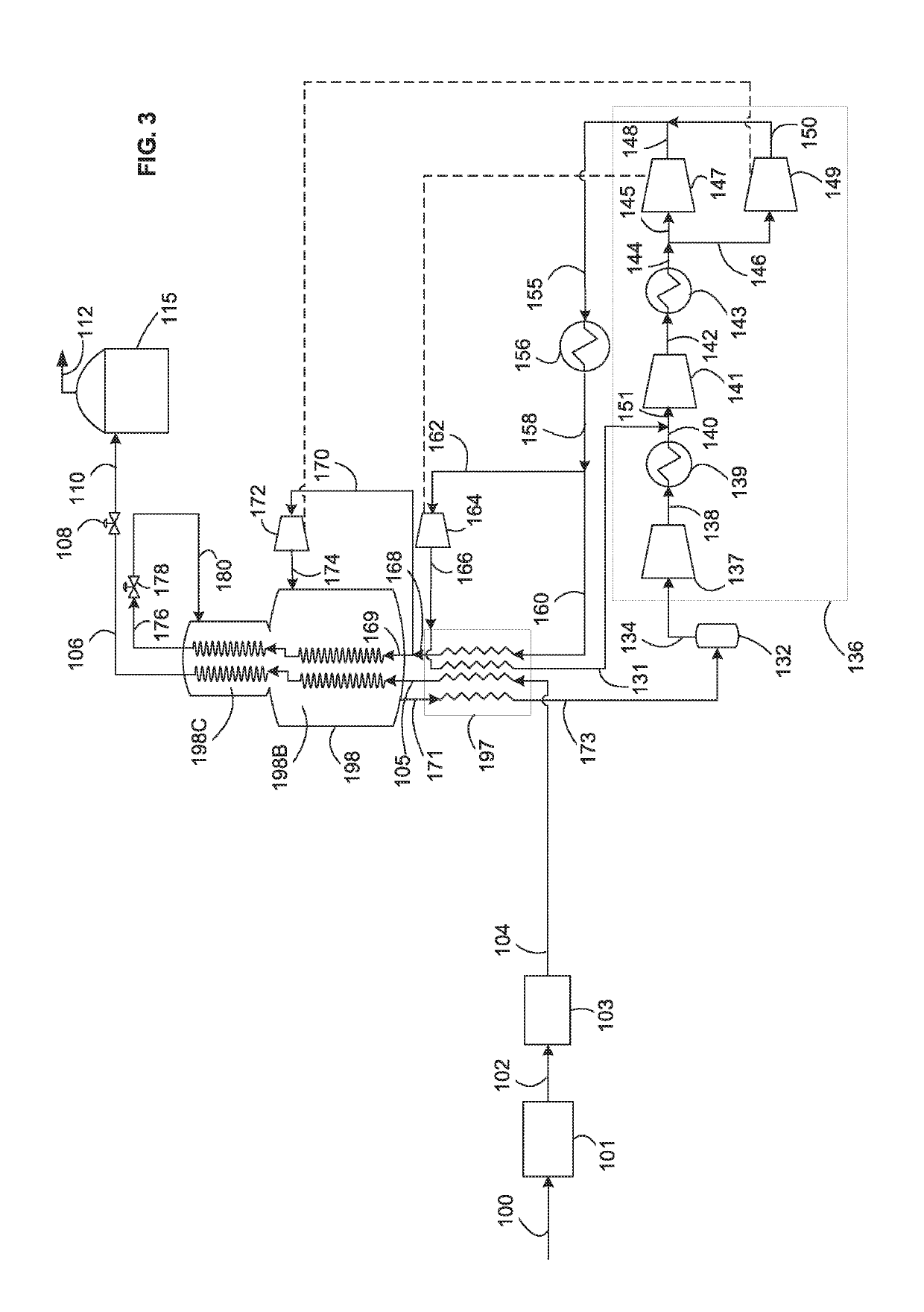
[0159]In this example, the method of liquefying a natural gas feed stream described and depicted in FIG. 3 was simulated. The results are shown in Table 1 and reference numerals of FIG. 3 are used.
[0160]In this example, the circulating refrigerant (as represented by the cooled compressed gaseous refrigerant stream 158) is 54 mole % nitrogen and 46 mole % methane. The ratio of refrigerant that provides evaporative refrigeration is 0.05. The pressure of the first strea...
example 2
[0162]In this example, the method of liquefying a natural gas feed stream described and depicted in FIG. 8 was simulated. The results are shown in Table 2 and reference numerals of FIG. 8 are used.
[0163]In this example, the circulating refrigerant (as represented by the cooled compressed gaseous stream 158) is 36 mole % nitrogen and 64 mole % methane. The ratio of refrigerant that provides evaporative refrigeration is 0.07. The pressure of the third stream of expanded cold refrigerant 174 is higher than that of the second str...
PUM
Abstract
Described herein are methods and systems for the liquefaction of a natural gasstream using a refrigerant comprising methane or a mixture of methane and nitrogen. The methods and systems use a refrigeration circuit and cycle that employs one or more turbo-expanders to expand one or more streams of gaseous refrigerant to provide one or more streams of at least predominantly gaseous refrigerant that are used to provide refrigeration for liquefying and / or precooling the natural gas, and a J-T valve to expand down to a lower pressure a stream of liquid or two-phase refrigerant to provide a vaporizing stream of refrigerant that provides refrigeration for sub-cooling.
Description
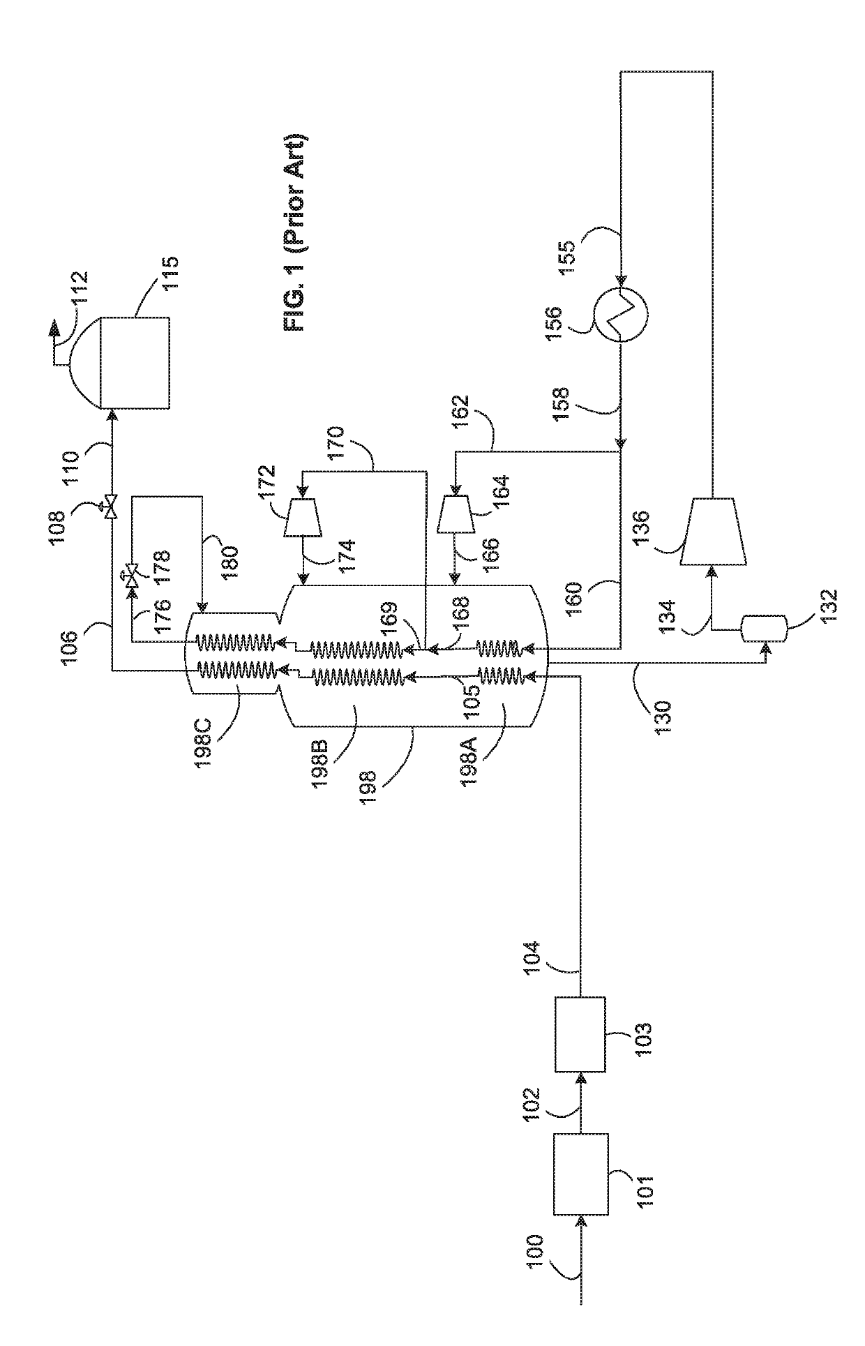
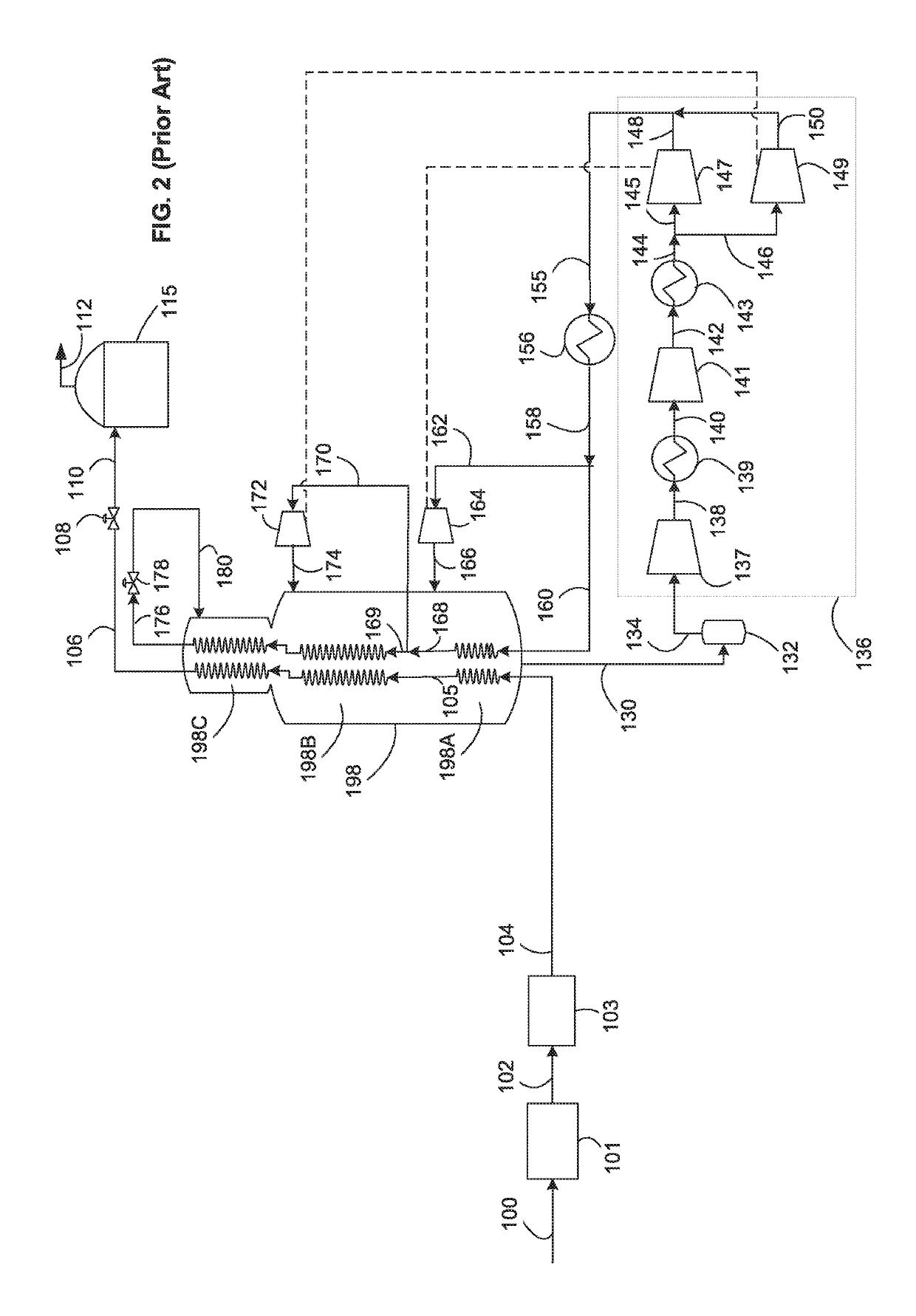
BACKGROUND[0001]The present invention relates to a method and system for liquefying a natural gas feed stream to produce a liquefied natural gas (LNG) product.[0002]The liquefaction of natural gas is an important industrial process. The worldwide production capacity for LNG is more than 300 MTPA, and a variety of refrigeration cycles for liquefying natural gas have been successfully developed, and are known and widely used in the art.[0003]Some cycles utilize a vaporizing refrigerant to provide the cooling duty for liquefying the natural gas. In these cycles, the initially gaseous, warm refrigerant (which may, for example, be a pure, single component refrigerant, or a mixed refrigerant) is compressed, cooled and liquefied to provide a liquid refrigerant. This liquid refrigerant is then expanded so as to produce a cold vaporizing refrigerant that is used to liquefy the natural gas via indirect heat exchange between the refrigerant and natural gas. The resulting warmed vaporized refri...
Claims
Application Information
Patent Timeline
Application Date:The date an application was filed.
Publication Date:The date a patent or application was officially published.
First Publication Date:The earliest publication date of a patent with the same application number.
Issue Date:Publication date of the patent grant document.
PCT Entry Date:The Entry date of PCT National Phase.
Estimated Expiry Date:The statutory expiry date of a patent right according to the Patent Law, and it is the longest term of protection that the patent right can achieve without the termination of the patent right due to other reasons(Term extension factor has been taken into account ).
Invalid Date:Actual expiry date is based on effective date or publication date of legal transaction data of invalid patent.
