Tethered aerial system and tether cable

a technology of tether cables and aerial systems, applied in the direction of generators/motors, lighter-than-air aircraft, transportation and packaging, etc., can solve the problems of increasing the system weight, unable to use aerostats with a volume of up to a few hundred cubic meters, and the cable is extremely heavy, so as to reduce the chance of attracting atmospheric discharges and optimize the technology

Active Publication Date: 2019-11-28
ALTAVE IND COMML E EXPORTACAO DE AERONAVES SA
View PDF12 Cites 10 Cited by
  • Summary
  • Abstract
  • Description
  • Claims
  • Application Information

AI Technical Summary

Benefits of technology

[0010]In order to overcome the deficiencies of the prior art as discussed above, the present invention proposes disruptive solutions applied in tethered aerial vehicles so that continuous operations with reduced chances of attracting atmospheric discharges are feasible.
[0011]Differently to what already forms part of the state of the art, the present invention innovates by disclosing an electric non-conductive cable with mechanical support fiber and gas tube, in addition to the fact that there is further the possibility of said cable may or may not have fiber optics.
[0012]In the case of the aerostats, which are tethered aerial vehicles of particular interest for this invention, the lifting gas of the aerostat disclosed herein can comprise hydrogen and helium, wherein the aerostat can be inflated preferably with helium and maintained inflated with hydrogen. To remain inflated, the gas is carried from the ground to the aerostat through a pneumatic tube.
[0013]The fact that the aerostat is able to keep supplied with lifting gas uninterruptedly allows for prolonged operations. The aerostat can be in operation for months or even years without being obliged to descend to be supplied. This is very important, for example, for telecommunications applications, wherein the signal service has to be continuous. Normally, balloons without on-operation supply technology do not last for more than 60 days, since there is no 100% tight material. This is due to the phenomenon of molecular effusion, and even with the use of metallic reservoirs, a gradual loss of gas mass from the interior is expected.
[0014]Regarding the power supply of the on-board electronics on the aerostat disclosed herein, the generation of energy by an on-board fuel cell is disclosed.
[0015]It is worthy to highlight that the hydrogen gas rising to the aerostat, in the present invention, has two purposes. This makes the technology optimized, and the use of energy from the fuel cell makes the aerostat sustainable, and this is a type of clean energy.

Problems solved by technology

The protection systems existing in the prior art comprise the arrangement of a copper layer surrounding the core of the cable, but customary regulations in the field of electrical grounding of structures report that the minimum gauge of a copper cable, to obtain the proper protection, is 35 mm, which makes the cable extremely heavy.
As an example, the weight for a cable of 250 meters, with the aforementioned copper protection, is 89.25 kg, which makes it impossible to use aerostats with a volume of up to a few hundred cubic meters.
In addition, a device is further needed to pick up the rays, which increases the system weight and causes damage to the balloon due to the high temperature to which lightning protectors are subjected when conducting electric current.
The sending and receiving of data is by fiber optics, wherein one of the main disadvantages of the disclosed content is that the protection provided against lightning consists of lightning arrester and grounding, the ground wire being extremely heavy, which may make the technology unfeasible in cases where the aerostat has less than 1000 cubic meters of lifting gas.
In this case, DC electrical energy comes from the energy generating ground base and data transmission is restricted to the use of fiber optics.
The powering of on-board systems is also disadvantageously made by sending energy from the ground, and the same energy is carried by electrical conductors.
In addition, the technology of WO2014 / 200566 A2 depends on the fiber optics to perform data transmission and reception, and, further disadvantageously, the intended protection is only by lightning arrester and grounding, wherein the ground wire is very heavy, which once again may make the technology unfeasible.

Method used


Image

  • Tethered aerial system and tether cable
  • Tethered aerial system and tether cable
  • Tethered aerial system and tether cable

Examples


Embodiment Construction

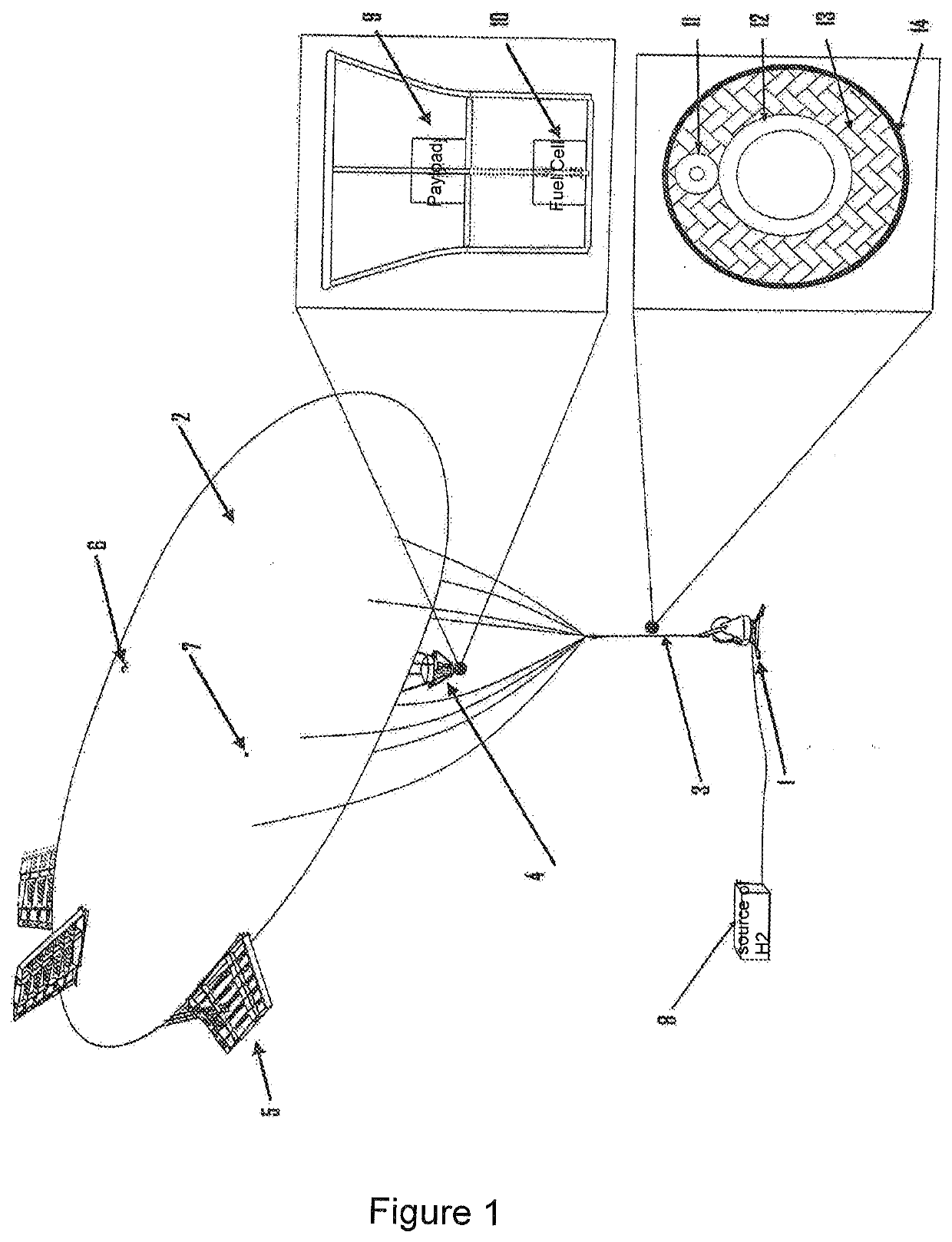
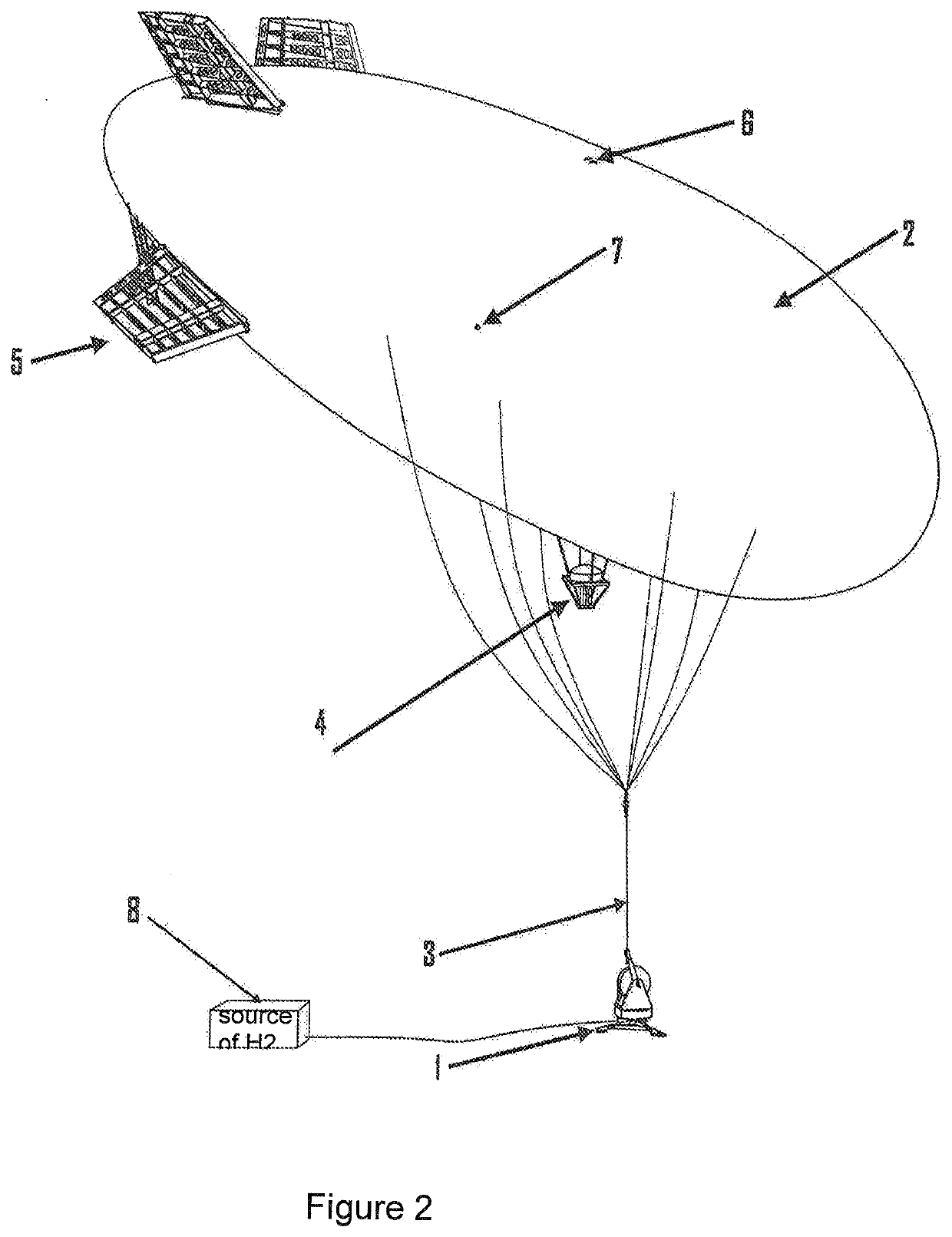
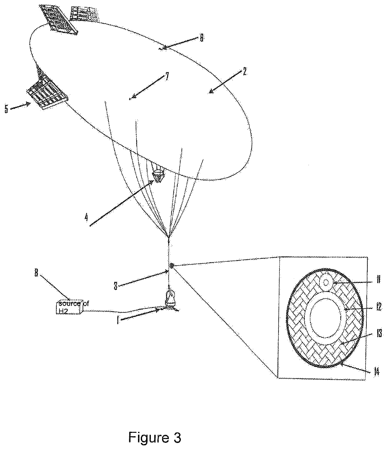
[0026]The present invention relates to a tethered aerial system comprising electrical energy self-generating means by fuel cell (10) for powering its on-board electronics, comprising an aerial vehicle (2) and payload (9), wherein said aerial vehicle (2) is connected to a gas source (8) on the ground by a tethering cable (3) which is an atmospheric discharge attraction preventer.

[0027]The aerial vehicle (2) may be selected from a group of options comprising: a lighter-than-air platform, a rotary wing aerial vehicle, a fixed wing aerial vehicle or a combination thereof.

[0028]When the option is made to use the lighter-than-air platform type aerial vehicle (2), which is the preferred option of the present invention, as illustrated in the examples of FIGS. 1 to 4, it is necessary to use the following additional elements with the system: a gondola (4), stabilizing empennages (5), a deflation device (6), and a light indicating device (7).

[0029]In this preferred option of the aerial vehicle...


PUM


Abstract

A tethered aerial system includes an on-board fuel cell for powering on-board electronics and a tether cable is less conductive than air. The tether cable includes a pipe for carrying a flow of gas to the fuel cell and/or maintain the gas level in a lighter-than-air platform, so that the tethered aerial system can remain operational for an extended period of time. The system is particularly applicable for maintaining communication links in remote areas, agriculture and applications in the IoT (Internet of Things), event coverage, interactive marketing, for post-disaster situations in rural areas and at mining sites or construction sites in remote environments. The present invention also is immune to rays.

Description

FIELD OF THE INVENTION[0001]The present invention addresses to the field of technologies related to tethered aerial vehicles and means for maintaining continuous operations with reduced chances of attracting atmospheric discharges.BACKGROUND OF THE INVENTION[0002]The tethered aerial vehicle, especially the tethered balloon or tethered aerostat, is the highlight for solutions in communication, military monitoring and monitoring of major events.[0003]In order to have on-board electronics with high operating time, the types of cable used for adaptation in these aerostats are generally electro-optical-mechanical or electro-mechanical. The on-board devices are powered electrically by the energy carried by these cables.[0004]From this principle, it is understood that the metal structure and electronic components on-board in the balloon and the ground are electrically connected, thus forming a lightning arrester for the electric discharges in its vicinity. Said electric connection causes t...

Claims


Application Information

Patent Timeline
Patent Type & Authority Applications(United States)
IPC IPC(8): B64B1/50B64B1/62B64B1/66B64F1/14H02N3/00
CPCB64B1/50B64B1/66B64F1/14H02N3/00B64B1/62B64U10/30B64U2101/20B64U50/32B64U10/60
Inventor AZEVEDO, BRUNO AVENA DENETO, ISMAEL JORGE COSTAJÚNIOR, GILSON VICENTE SOARESFERREIRA, ARTHUR SILVA COSTA
Owner ALTAVE IND COMML E EXPORTACAO DE AERONAVES SA
Why Eureka
Try Eureka