Projection system and projector

a projection system and projector technology, applied in the field of projection systems and projectors, can solve the problems of preventing the distortion of the image, affecting the quality of the image, and damage to the lens unit and peripheral components, so as to reduce the cost of the lens, restrain the temperature rise, and reduce the weight

Active Publication Date: 2019-11-28
SEIKO EPSON CORP
View PDF0 Cites 5 Cited by
  • Summary
  • Abstract
  • Description
  • Claims
  • Application Information

AI Technical Summary

Benefits of technology

[0008]In the invention, it is preferable that the second optical system has a plurality of lenses, that at least a lens on a most enlarging side, of the plurality of lenses, has a substantially arcuate outer shape on one side in a direction orthogonal to an optical axis of the second optical system and has a substantially arcuate outer shape that is partly missing on the other side, and that the intermediate image is formed at a position shifted from the center of the effective image forming area when substantially all of the light enters the lenses except the missing part of the lens on the most enlarging side. Since the part that is not used is cut off, lighter weight and lower cost of the lens can be achieved. Also, it is possible to restrain a temperature rise due to light becoming incident on the cut-off area of the lens and striking the lens barrel or the like as the position of the replacement lens unit forming the projection system goes off the display range. Thus, there is little risk of the lens unit being damaged.
[0009]In the invention, it is preferable that the light-shielding area includes an area on the side opposite to the side to which the intermediate image is shifted, within the range of the effective image forming area. In this way, in the case where the optical shift system is employed, the area on the side opposite to the side where the intermediate image shifts is shielded from light. Thus, unwanted light can be cut off efficiently, using the light-shielding mask with a simple shape.
[0010]In the invention, it is preferable that the side to which the intermediate image is shifted from the center of the effective image forming area at the image forming position is one side in a first direction orthogonal to the optical axis of the first optical system, that a direction orthogonal to the optical axis of the first optical system and the first direction is a second direction, and that the light-shielding area is an area surrounding the other side in the first direction of the intermediate image and both sides in the second direction of the intermediate image, within the range of the effective image forming area. In this way, unwanted light can be cut off in three directions surrounding the intermediate image. Thus, the majority of the unwanted light can be cut off.
[0011]The second optical system has at least one resin lens. Using the resin lens, it is possible to easily prepare an aspheric lens, easily prepare a lens with a non-circular outer shape, and also achieve lighter weight of the projection system. Also, even if the position of the projection system goes off the display range, the light that is off the display range is blocked before the resin lens. Therefore, a temperature rise in the resin lens due to the irradiation of the lens barrel or the like around the resin lens with unwanted light can be restrained. Thus, there is little risk of the resin lens being damaged.
[0012]In the invention, the light-shielding mask has a shape along a plane perpendicular to the optical axis. Thus, the shape of the light-shielding mask can be simplified.
[0013]In the invention, the light-shielding mask has a shape that follows a field curvature of the intermediate image. For example, a light-shielding film formed on a surface of the lens situated on the nearest side to the image in the first optical system is used as the light-shielding mask. Thus, the light-shielding area can beset, following the field curvature. Therefore, the light-shielding area can be set along the contour of the intermediate image. Thus, the image emitted from the projection system can be sharpened and a reduction in the quality of the projected image can be restrained.

Problems solved by technology

In the case where the optical shift system is used, restraining a distortion of the image is a problem to be solved.
Therefore, if a part or the entirety of the projection system is made up of a replacement lens unit, an unintended site may be irradiated with light at the time of replacement and this may cause damage to the lens unit and peripheral components.
In such cases, damage may occur at a site having a high temperature due to the irradiation with the light.
Also, even if the position of the projection system goes off the display range, the light that is off the display range is blocked before the resin lens.

Method used


Image

  • Projection system and projector
  • Projection system and projector
  • Projection system and projector

Examples


embodiment 1

Overall Configuration

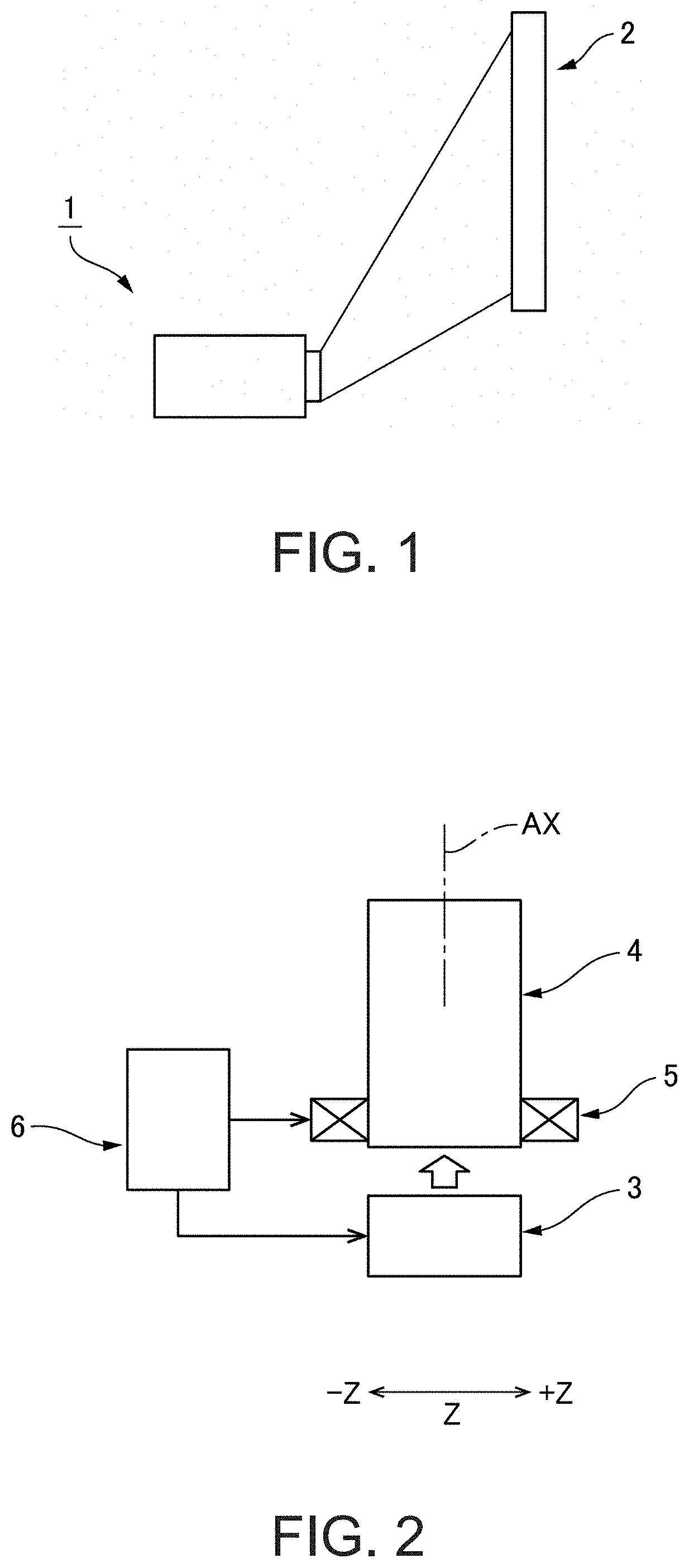
[0027]FIG. 1 is an explanatory view schematically showing the state of use of a projector 1 according to Embodiment 1 to which the invention is applied. FIG. 2 is an explanatory view schematically showing a schematic configuration of the projector 1 according to Embodiment 1. As shown in FIG. 1, the projector 1 according to Embodiment 1 projects image light toward a screen 2. The projector 1 is a short throw projector which generates wide-angled image light, using a lens with a wide angle of view or the like, and projects the generated image light onto the screen at a short projection distance. The image light emitted from the projector 1 can display an image with little distortion even if the image light enters at a steep angle on the screen 2.

[0028]As shown in FIG. 2, the projector 1 has an image generation unit 3, a projection system 4, a lens shift mechanism 5, and a control unit 6. In the projector 1, the projection system 4 is removable. These mechanisms a...

modification 1

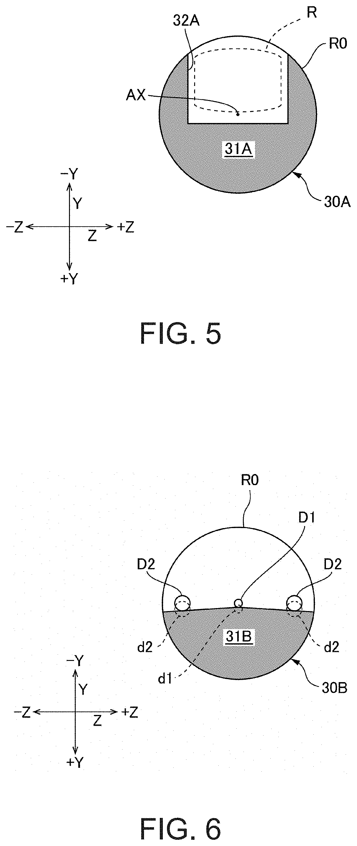
[0047]FIG. 5 is an explanatory view of a light-shielding area 31A by a light-shielding mask 30A of Modification 1. In Embodiment 1, only the area in the +Y direction from the intermediate image R is shielded from light, whereas the light-shielding area 31A by the light-shielding mask 30A in Modification 1 is an area covering three directions, that is, the +Y direction side of the intermediate image R (that is, the side opposite to the side to which the intermediate image R is shifted from the center of the effective image forming area R0), and both sides in the second direction Z of the intermediate image R (that is, both sides in the second direction Z orthogonal to the direction of the optical axis AX and the first direction Y), within the range of the effective image forming area R0. The light-shielding area 31A is marked off by a boundary 32A in a recessed shape that is recessed in the +Y direction. Thus, not only unwanted light in the direction of image height but also unwanted...

embodiment 2

[0052]FIG. 9 is a cross-sectional configuration view of a projection system 104 according to Embodiment 2. Hereinafter, only the differences between the projection system 104 of Embodiment 2 and that of Embodiment 1 will be described. While the optical path of the projection system 4 of Embodiment 1 is not bent, the projection system 104 of Embodiment 2 is provided with flat-surface mirrors 8 and 9 in the course of its optical path. The mirrors 8 and 9 change the direction of the optical path by 90 degrees each. Therefore, the exiting direction of the image light is changed by 180 degrees. Also, while the above configuration has flat-surface mirrors for changing direction, curved-surface lenses may be employed.

[0053]The projection system 104 of Embodiment 2 forms an intermediate image at a halfway point, as in Embodiment 1. The image forming position P of the intermediate image is situated to the exiting side of the mirrors 8 and 9. However, the image forming position P of the inter...


PUM


Abstract

A projector projects image light generated by an image generation unit, as an enlarged image via a projection system. The incident position of the image light on the projection system is moved by a lens shift mechanism. The projection system forms an intermediate image in the course of the optical path. A light-shielding mask is provided at an image forming position of the intermediate image. A light-shielding area by the light-shielding mask includes an area that does not overlap the intermediate image within a range of an effective image forming area at the image forming position of the intermediate image. For example, the light-shielding area is an area on the side opposite to the side to which the intermediate image is shifted, of the circular effective image forming area.

Description

BACKGROUND1. Technical Field[0001]The present invention relates to a projection system, and a projector which projects an image or the like, using a projection system.2. Related Art[0002]Traditionally, a projector which projects an image generated using a liquid crystal light valve and a digital micromirror device (DMD) or the like, as an enlarged image on a screen via a projection system, is used. Japanese Patent No. 5266642 (Document 1) discloses a projector of this type (front-projection display device). In the front-projection device of Document 1, a DMD is used as an image generation unit, and a projection system has a relay lens group and a wide-angle lens group. Image light emitted from the DMD travels through a prism, enters the relay lens group, has its optical path bent by 90 degrees by an intermediate prism, and subsequently enters the wide-angle lens group. The image light emitted from the wide-angle lens group is corrected so that an image without any distortion can be ...

Claims


Application Information

Patent Timeline
Patent Type & Authority Applications(United States)
IPC IPC(8): G02B13/16H04N5/74G03B21/14G02B5/00
CPCG02B5/003G02B13/16G03B21/14G03B21/54H04N9/317G02B5/00G02B13/00G03B21/00H04N5/7416
Inventor MORI, TAKATERUNARIMATSU, SHUJISHIOKAWA, KOJI
Owner SEIKO EPSON CORP
Why Eureka
Try Eureka