Dynamic range of motion orthosis

a dynamic range of motion and shoulder technology, applied in the field of shoulder and arm orthotics, can solve the problems of limited range of motion (with or without muscular control), reduced motor skills, and atrophy, and achieve the effect of facilitating rotation of the flexion-extension assembly

Active Publication Date: 2019-12-05
DAVIES SEKLE BRANDON O
View PDF0 Cites 20 Cited by
  • Summary
  • Abstract
  • Description
  • Claims
  • Application Information

AI Technical Summary

Benefits of technology

[0028]And, in yet another contemplated embodiment, a flexion-extension assembly may connect the torso assembly to the upper arm assembly. The flexion-extension assembly defines a flexion-extension assembly axis. The flexion-extension assembly facilitates rotation of the flexion-extension assembly around the flexion-extension assembly axis.

Problems solved by technology

This is typically accompanied by some degree of atrophy and weakness in the effected muscles, a limited range of motion (with or without muscular control), and diminished motor skills, especially when nerve impairments result in tremors.
Unfortunately, current physical therapy and resistance training techniques are generally limited in their capacity to provide the greatest possible recuperation of muscular strength and range of motion.
This is due to it being extremely difficult, to impossible to achieve the mechanics of the necessary exercise movements to stop the stronger muscles of the arm and shoulder from compensating for the weaker ones.
In this instance, the stronger muscles do the majority of the work that creates the motion, and the weaker ones, not being in an appropriate anatomical configuration, do not receive enough stimulation to realize a significant amount of recovery.
Additionally, attempts at putting the arm in such anatomical positions using traditional equipment may put more resistance on the arm than it is presently capable of moving, instead of putting the arm in positions where the resistance created by the weight of the arm itself can be started with before adding any weight beyond that.
Furthermore, even when the weaker muscles are put in a position where they're forced to do the majority of the work, strength may be lacked to execute any movement.
The ineffectiveness is also due to the inability to provide a prolonged stretch to the necessary muscles of the arm and shoulder when needed.
Additionally, it means that the bulk of the recovery to impaired muscles is achieved through motion rather than statics.
Secondly, it can be put on and taken off without assistance if the user has another sufficiently functioning arm.
Shoulder adduction, abduction, flexion, and extension and elbow flexion or extension are degrees of freedom that may also become impaired by injury.

Method used


Image

  • Dynamic range of motion orthosis
  • Dynamic range of motion orthosis
  • Dynamic range of motion orthosis

Examples


third embodiment

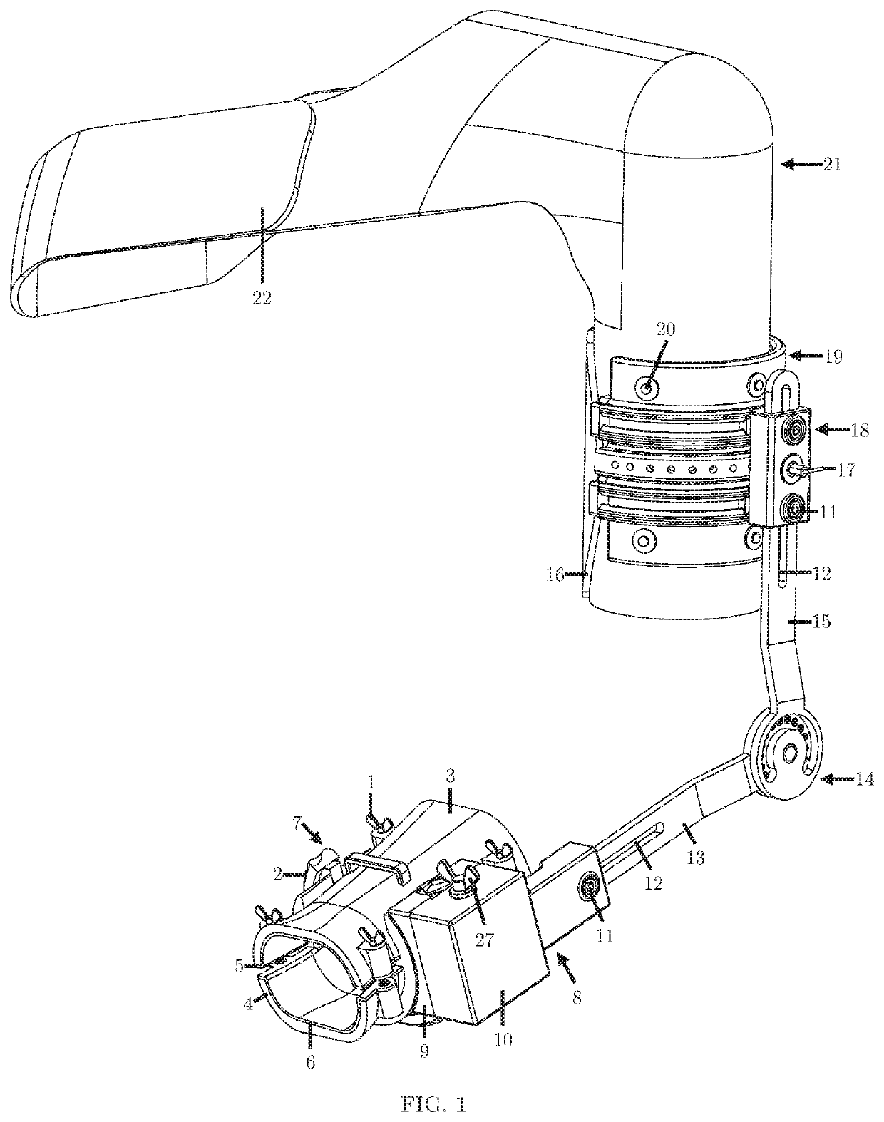
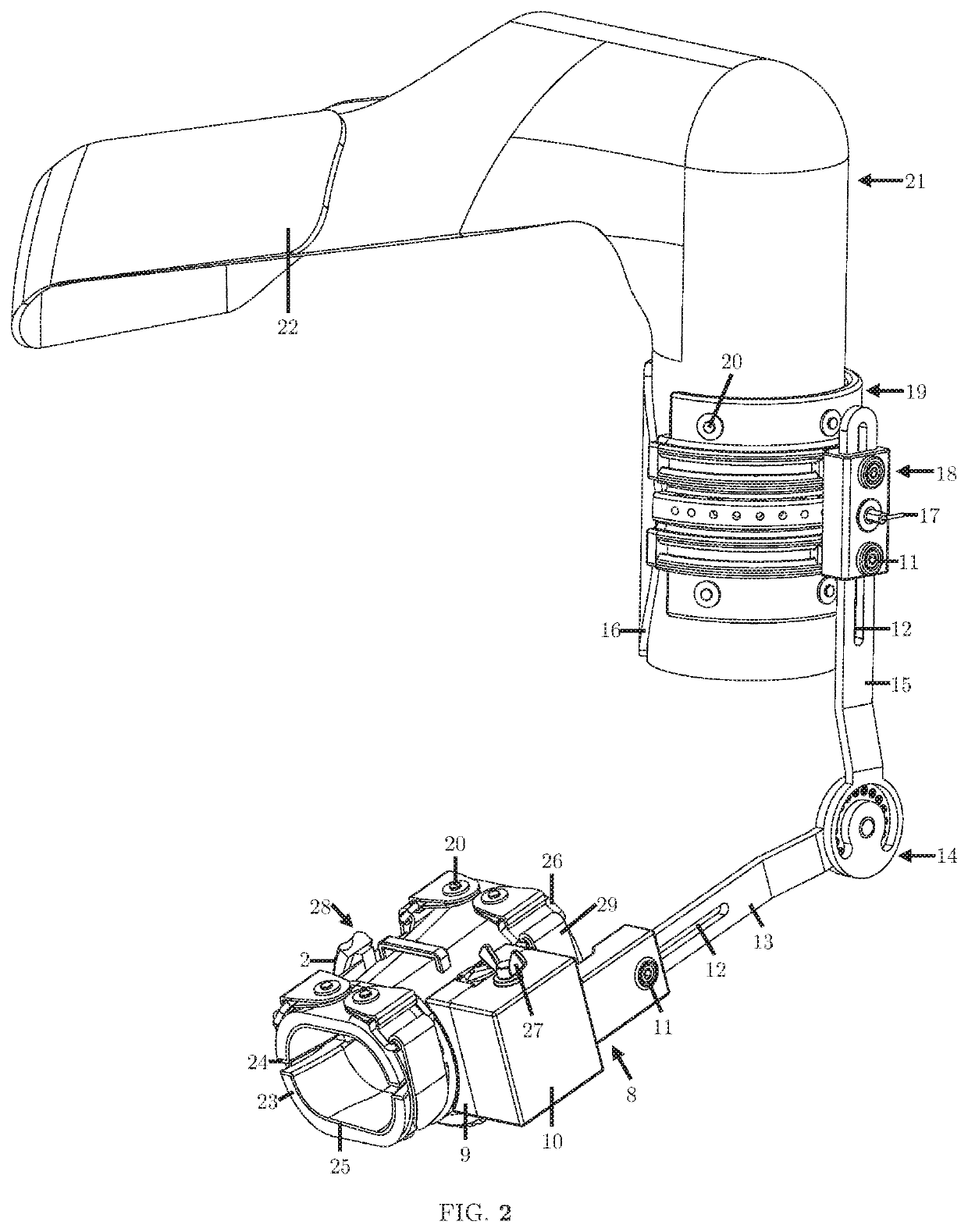
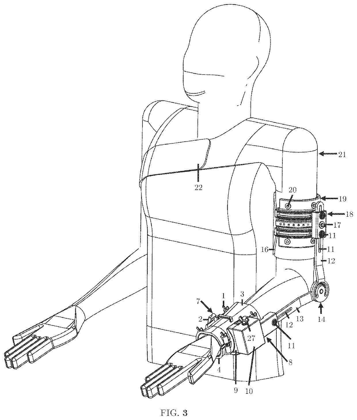
[0262]the orthosis, orthosis-ROM, is illustrated in FIG. 59. For simplicity and conciseness, it is being referred to as orthosis-ROM (where ROM stands for range of motion) because it is the embodiment that allows the arm and shoulder's full range of motion to be controlled.

[0263]Once again, for the sake of convenience, “orthosis” will be used to collectively refer to either embodiment of the orthosis, which includes orthosis-thumb, orthosis-strap, and orthosis-ROM. Similarly, “wrist cuff assembly” will be used to collectively refer to either embodiment of the wrist cuff assembly, which includes the wrist cuff assembly that uses thumbscrews, the wrist cuff assembly that uses straps, and a wrist cuff assembly that uses ratchets and pawls. The wrist cuff assembly that uses ratchets and pawls is a third embodiment that's being introduced and will be referred to as the ratchet lock wrist cuff assembly.

[0264]Referring now to the third embodiment of the present invention in more detail, in...

first embodiment

[0313]The rotary motion carriage ring 208, illustrated in FIG. 93, performs almost the same function as the linear motion carriage 54 of the orthosis of the present invention. It has the basic shape of a cylindrical shell with two diametrical steps and a shoulder 252 that is cut into the inner annulus of the side with the largest diameter step. The outside surface of the smaller step has a set of dog clutch teeth 249 that run parallel to the axis of the shell and match the geometric profile of the clutch teeth 234 on the internal-external rotation worm gear 230. Along the teeth 249 there are a number of equally-circumferentially spaced blind, threaded holes 250 whose axes are normal to the axis of the shell. Each threaded hole 250 has a ball-nose spring plunger 217 threaded into it and the ball of each plunger 217 extends slightly beyond the face of its accompanying tooth. The threaded hole 250 and the ball-nose spring plunger 217 are contemplated to use 4-48 threads but any size ma...

second embodiment

[0342]The front and rear spring rings 493, 501, illustrated in FIG. 150, have the basic shape of a cylindrical shell sector whose included angle is slightly less than the smallest included angle of the lower wrist cuff's 494“circumscribed” cylinder along its axial length. As shown in FIG. 138, this ensures that the ends do not go pass those of the “circumscribed” cylinder. The inner cylindrical surface of each ring 493, 501 has a round rail slot 563 wrapped around its perimeter that corresponds to the round rails 586 of the front and rear wrist cuff rails 522, 523, 524, 513, 514, 515. The outer cylindrical surface of each rail 493, 501 has a dovetail slot. 560 wrapped around its perimeter that corresponds to the dovetails 478 of the supination-pronation gearbox assembly 140.

[0343]The worm gear ring 506, illustrated in FIG. 151, has the basic shape of a cylindrical shell sector whose included angle is equal to that of the spring rings 493, 501. The inner cylindrical surface of the wo...


PUM


Abstract

An orthosis provides a wearer at least one of forearm supination, forearm pronation, shoulder internal rotation, shoulder external rotation, shoulder adduction, shoulder abduction, shoulder flexion, shoulder extension, elbow flexion, and elbow extension. It includes a shoulder assembly adapted to be secured to a wearer's shoulder and an upper arm assembly connected to the shoulder assembly and adapted to be secured around a wearer's upper arm. The upper arm assembly defines an upper arm assembly axis. A wrist assembly is adapted to be secured around a wearer's wrist. The wrist assembly defines a wrist assembly axis. A splint arm assembly includes an upper splint arm, a lower splint arm, and a pivot pivotally connecting the upper splint arm to the lower splint arm. The upper splint arm adjustably connects to the upper arm assembly and the lower split, arm adjustably connects to the wrist assembly.

Description

FIELD OF THE INVENTION[0001]The present invention is in the technical field of shoulder and arm orthopedics. More specifically, the present invention is in the technical field of shoulder and arm orthotics, which loosely relates to and overlaps the technical fields of splint and brace making.[0002]The present invention relates to an orthotic device, to be worn by a person, that provides an adjustable amount of forced forearm pronation or supination and an adjustable amount of forced shoulder internal or external rotation. Use of the device provides a means for muscular rehabilitation to users, with some degree of paralysis in the arm or shoulder, through the conjunctional use of resistance training and the stretches provided through any number of possible degrees of motion. In addition to supination, pronation, internal rotation, and external rotation, it may also provide an adjustable amount, of forced shoulder adduction, abduction, flexion, or extension and, with a lockable elbow,...

Claims


Application Information

Patent Timeline
Patent Type & Authority Applications(United States)
IPC IPC(8): A61F5/01A61H1/02
CPCA61H1/0281B25J9/0006A61F2005/0165A61F2005/0146A61F5/013A61H2205/062A61H2201/1638A61H2201/1261A61H1/0277A61H2201/1659A61H2205/06A61H1/0285A61H2201/1454A61H2205/065A61H2201/1676A61H2201/165A61H2201/5053
Inventor DAVIES-SEKLE, BRANDON O.
Owner DAVIES SEKLE BRANDON O
Why Eureka
Try Eureka