Vacuum Motor, Surgical Drive System, And Method For Operating A Vacuum Motor

Active Publication Date: 2019-12-05
HERAEUS MEDICAL
View PDF3 Cites 1 Cited by
  • Summary
  • Abstract
  • Description
  • Claims
  • Application Information

AI Technical Summary

Benefits of technology

[0012]Accordingly, it is an object of the present invention to overcome the disadvantages of the known references. In particular, it is an object of the invention to provide a vacuum motor that is relatively inexpensive and easy to manufacture, works reliably, can be used broadly, and achieves sufficient power with the aid of a negative pressure source of the type that is available in hospitals for th

Problems solved by technology

The devices used for debridement are contaminated with tissue residues and microbial germs after the debridement.
Moreover, the valve element is associated with the risk of there being a dead center out of which the vacuum motor may not be run without assistance.
The system is disadvantageous in that the valve element, in the opened state, can provide only a small free cross-section of flow.
As a result, the force that can be generated by the pump is limited and there is a risk of there being a dead center out of which the pump cannot start up again without assistance.
Moreover, air may ingress f

Method used


Image

  • Vacuum Motor, Surgical Drive System, And Method For Operating A Vacuum Motor
  • Vacuum Motor, Surgical Drive System, And Method For Operating A Vacuum Motor
  • Vacuum Motor, Surgical Drive System, And Method For Operating A Vacuum Motor

Examples


Example

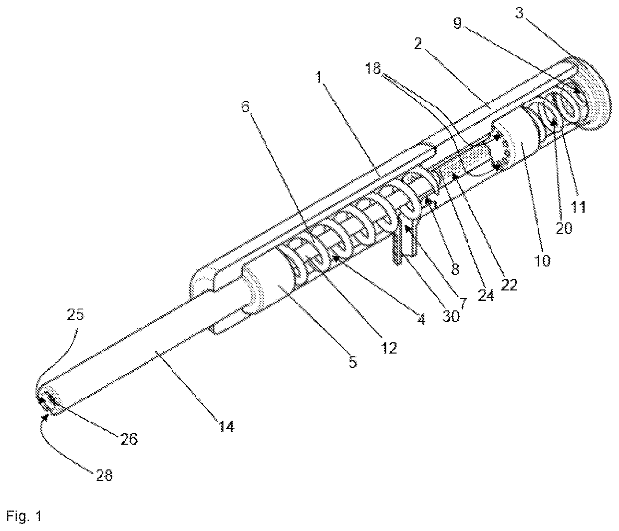
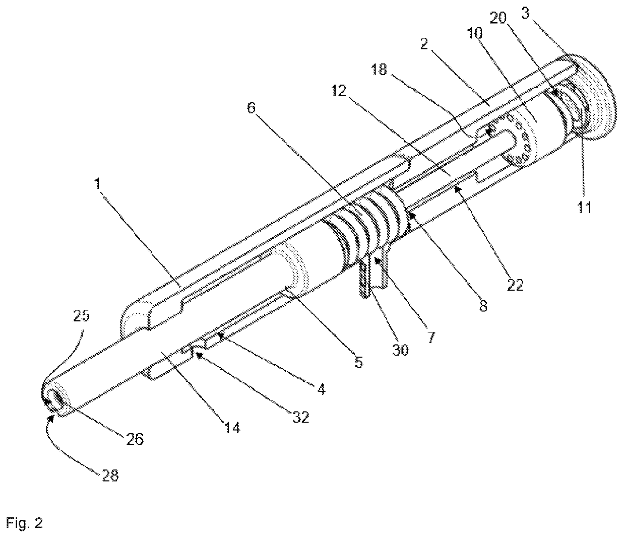
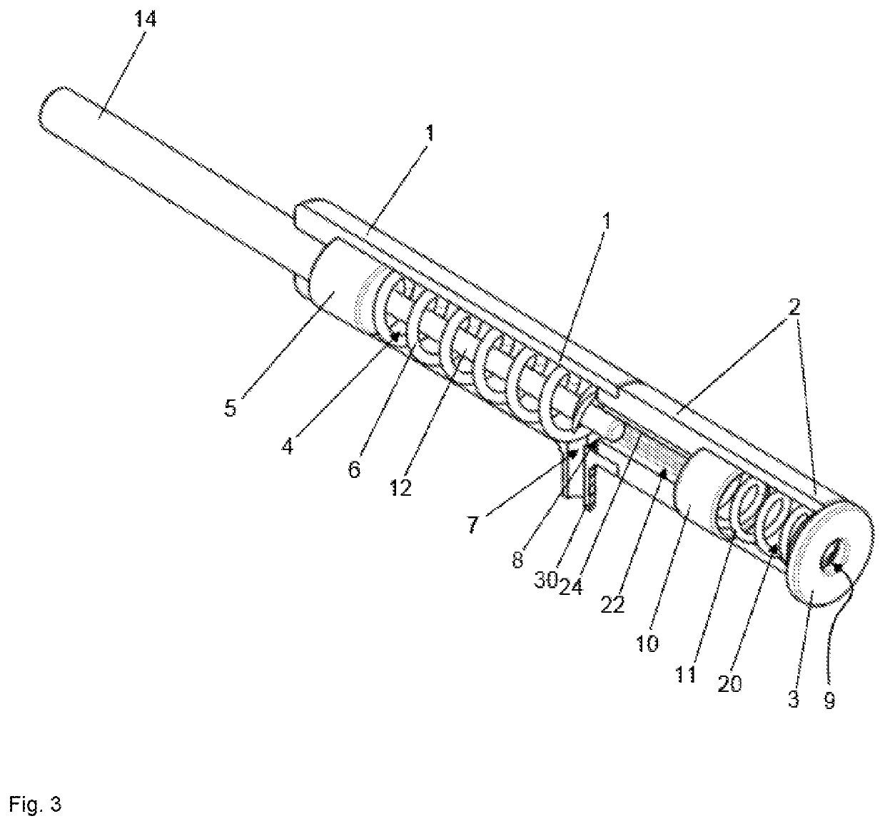
[0143]FIGS. 1 to 6 show depictions of a vacuum motor according to the invention. FIGS. 7 to 10 show a surgical drive system according to the invention with a vacuum motor of this type, as the one shown in FIGS. 1 to 6. The front side of the vacuum motor and of the surgical drive system and thus the equally oriented front sides of the parts of the vacuum motor and of the surgical drive system are shown on the left front in FIGS. 1, 2, 6, 7, and 10 to 12 (projecting out of the image plane in the direction of the observer), on the left back in FIG. 3 (into the image plane, away from the observer), on the left in FIGS. 4, 5, and 8, and also on the left in FIG. 9, whereby the front end is not shown in FIG. 9. Accordingly, the front side is basically oriented in the direction of the left side in the depictions. While one also views the front sides of the vacuum motor and of the surgical drive system in FIGS. 1, 2, 6, 7, and 10 to 12, FIG. 3 shows the rear side of the vacuum motor.

[0144]Th...


PUM


Abstract

A vacuum motor has a piston that linearly oscillates in the internal space of a housing. A gas outlet and a gas inlet (supplying ambient air) located in the housing terminate in the space between the piston and the housing rear side. The piston never covers the outlet or inlet. A valve body closes the inlet. A pestle moves within the housing between the piston and valve body. When the piston moves toward the rear side of the space, the valve body moves against the force of a spring and opens the inlet. The free cross-section of the opened inlet is at least equal in size to the free cross-section of the outlet. A surgical drive system, a medical lavage system, and a medical device for brushing, rasping or sawing of tissue or bone—all include the vacuum motor. Also disclosed is a method for operating the vacuum motor.

Description

RELATED APPLICATION[0001]This application claims the benefit of priority to German Patent Application Number DE 10 2018 208 567.6, filed on May 30, 2018, the contents of which are incorporated in this application by reference.TECHNICAL FIELD[0002]The invention relates to a vacuum motor, a surgical drive system comprising the vacuum motor, a medical lavage system for the debridement of soft tissue and / or bone tissue comprising the vacuum motor, and a medical device for brushing, rasping, or sawing of soft tissue and / or bone tissue comprising the vacuum motor as well as to a method for operating a vacuum motor. The vacuum motor is suitable for driving medical devices for lavage and debridement of soft and bone tissue. The medical devices driven by the vacuum motor are preferably intended for single use for hygienic reasons. Moreover, a method for generating oscillating linear motions is proposed.BACKGROUND OF THE DISCLOSURE[0003]Regrettably, septic revisions of articular endoprosthese...

Claims


Application Information

Patent Timeline
IPC IPC(8): A61M1/00A61B17/16
CPCA61B2217/005A61B2017/320064A61B17/1644A61M1/0068F01B29/10F01B25/10F01B23/06F01B23/08A61M3/0254A61B17/00A61B2017/00398A61B2017/00561A61B17/142A61B17/1659A61B2017/320028A61B2017/00544A61B17/32002A61B2017/320012A61B2017/00761
Inventor VOGT, SEBASTIANKLUGE, THOMAS
Owner HERAEUS MEDICAL
Why Eureka
Try Eureka