Light projecting apparatus

Active Publication Date: 2019-12-05
SHARP FUKUYAMA LASER CO LTD
View PDF0 Cites 0 Cited by
  • Summary
  • Abstract
  • Description
  • Claims
  • Application Information

AI Technical Summary

Benefits of technology

The present invention reduces the number of optical fibers that connect a light source unit and a light projecting unit, making management against breakage of the optical fiber easier. Additionally, a fiber-breakage countermeasure mechanism is provided to detect and quickly address breakage of the optical fibers to prevent exposure to a laser beam. These features contribute to a safer and more manageable laser system.

Problems solved by technology

For example, when the technology described in Japanese Unexamined Patent Application Publication No. 2017-100635 is used for a street lamp or the like, if the light source is a laser light source, because many people pass by the street lamp on a road, if only one of the large number of optical fibers breaks, a laser beam leaks from the section of the broken fiber, and a nearby person is very likely to be exposed to the laser beam.

Method used


Image

  • Light projecting apparatus
  • Light projecting apparatus
  • Light projecting apparatus

Examples


first embodiment

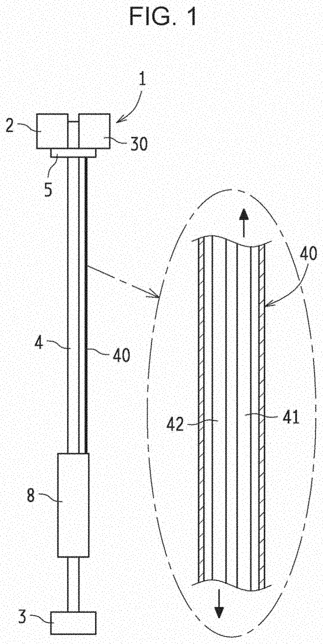
[0027]FIG. 1 illustrates a first embodiment in which the present invention is applied to a light projecting apparatus for a monitoring camera.

[0028]In the figure, a light projecting apparatus 1 projects a laser beam to a field-of-view region that a monitoring camera 2 monitors and illuminates the field-of-view region. The monitoring camera 2 is disposed on a support base 5 at an upper end of a pole 4 that is set on a base 3. The monitoring camera 2 is a near-infrared monitoring camera.

[0029]The light projecting apparatus 1 includes an operation box 8 that is disposed at a position on the pole 4 near the ground, and a light-projecting optical module (light projecting unit) 30 that is disposed side by side with the monitoring camera 2 on the support base 5 at the upper end of the pole 4. The operation box 8 and the light-projecting optical module 30 are connected to each other by a cable 40.

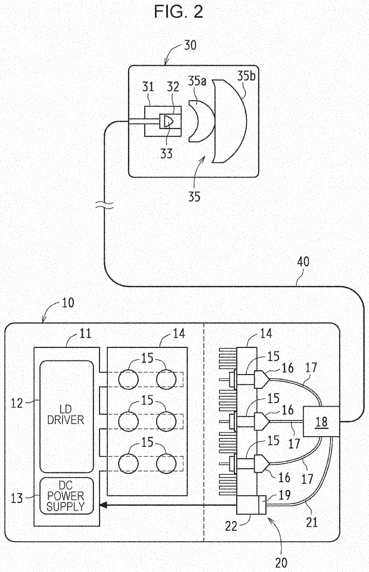
[0030]As illustrated in FIG. 2, a laser-light-source module (light source unit) 10 is contained...

second embodiment

[0051]FIGS. 4 and 5 illustrate a second embodiment in which the present invention is applied to a light projecting apparatus for a near-infrared monitoring camera.

[0052]In the first embodiment, the feedback optical fiber 42 is disposed in the cable 40, and one near-infrared laser beam transmitted to the light-projecting optical module 30 is fed back to the laser-light-source module 10. In the present embodiment, an electric signal indicating that one near-infrared laser beam is transmitted to the light-projecting optical module 30 is output to the laser-light-source module 10.

[0053]To be specific, as illustrated in FIG. 5, a photodiode 50 is disposed in the light-projecting optical module 30 as a part of the fiber-breakage countermeasure section 20. The photodiode 50 detects one near-infrared laser beam transmitted from one transmission optical fiber 41, which is disposed in the cable 40, and outputs an electric signal.

[0054]As illustrated in FIG. 4, one electric wire 43 is disposed...

third embodiment

[0059]FIGS. 6 and 7 illustrate a third embodiment in which the present invention is applied to a light projecting apparatus for a near-infrared monitoring camera.

[0060]In the second embodiment, an electric signal generated when the photodiode 50, which is disposed in the light-projecting optical module 30, detects light is fed back to the laser-light-source module 10 through the feedback electric wire 43. In the present embodiment, feedback is performed by using a radio signal.

[0061]To be specific, in FIG. 7, in the light-projecting optical module 30, in addition to the photodiode 50, which detects a laser beam from the transmission optical fiber 41 for transmitting a laser beam, a short-distance wireless oscillator 55 is disposed near the photodiode 50. The wireless oscillator 55 receives an electric signal when the photodiode 50 detects light and outputs a radio signal toward the laser-light-source module 10.

[0062]As illustrated in FIG. 6, in the cable 40, the feedback optical fib...


PUM


Abstract

In a light projecting apparatus including a laser light source, a light projecting apparatus 1 is divided into a laser-light-source module 10 and a light-projecting optical module 30. In the laser-light-source module 10, laser beams from a plurality of laser light sources 15 are combined by a beam combiner 18. The laser-light-source module 10 and the light-projecting optical module 30 are connected to each other by an optical fiber in a cable 40. A laser beam formed by the beam combiner 18 is transmitted through the optical fiber to the light-projecting optical module 30, received by a fiber receptacle 31, and projected. In the laser-light-source module 10, a fiber-breakage countermeasure section 20 that detects breakage of the optical fiber and takes countermeasures against the breakage is disposed.

Description

BACKGROUND OF INVENTIONField of Invention[0001]The present invention relates to improvement of a light projecting apparatus including a laser light source.Related Art[0002]Japanese Unexamined Patent Application Publication No. 2017-100635 describes an existing technology related to a light projecting apparatus. The Publication describes a structure in which, in a railroad crossing light or the like, a light source is set near the ground, and light of the light source is guided through an optical fiber, which is disposed along a main pole of the railroad crossing light, and a signal lamp is lit at a high position on the main pole. As the optical fiber, an optical cable that is composed of a bundle of a large number of optical fibers is disposed so as to extend from the light source near the ground to the signal lamp at the high position.[0003]Japanese Unexamined Patent Application Publication No. 2015-50225 discloses a technology that includes a plurality of laser light sources that ...

Claims


Application Information

Patent Timeline
IPC IPC(8): H05B37/02F21V8/00G01M11/00
CPCG01M11/33G02B6/0008G02B6/0006H05B37/0227F21S8/00F21V5/04F21V23/003F21V2200/10G01M11/31H05B45/00H05B47/125H05B47/175Y02B20/40
Inventor HAYASE, YUKIHIDEMORIGAMI, MASANORI
Owner SHARP FUKUYAMA LASER CO LTD
Why Eureka
Try Eureka