Composite photocatalysts, method for making the same and application thereof

a photocatalyst and composite technology, applied in the field of composite photocatalysts, can solve the problems of low catalytic efficiency of the photocatalyst in the actual applicant, the infancy stage of the artificial nanomotor, and the difficulty of researchers in building more complex nanomotors to complete more complex work, etc., to achieve high photocatalytic activity, simple steps, and easy implementation

Active Publication Date: 2019-12-19
HANGZHOU TONG KING ENVIRONMENT TECH CO LTD
View PDF8 Cites 49 Cited by
  • Summary
  • Abstract
  • Description
  • Claims
  • Application Information

AI Technical Summary

Benefits of technology

[0051]The method has simple steps, is easy to implement, and can be industrialized.
[0052]The composite photocatalyst provided in this application has high photocatalytic activity and can be applied to degrade organic matter.

Problems solved by technology

However, artificial nanomotors are still in infancy stage, compared to the diversity of macroscopic motors that are almost ingrained in all aspects of technology.
How to build more complex nanomotors to complete more complex work is still a challenge for researchers.
(1) When the photocatalyst is irradiated under light, a plurality of electron-hole pairs are generated inside and on the surface of the photocatalyst. Due to the extremely short time, majority of the plurality of electron-hole pairs are combined and quench before diffusing to the surface. This leads to low catalytic efficiency of the photocatalyst in actual applicant.
(2) Since the photocatalyst in nanometer scale are easy to agglomerate, the surface area of the photocatalyst is reduced, which is not good for separation of electron and hole, resulting in catalytic activity greatly reduced and low photocatalytic efficiency.
(3) The photocatalyst can be used with a limited carrier. When it is supported on an inorganic carrier, the effective catalytic area is a plane and small, therefore the catalytic efficiency is low. When it is supported on an organic carrier, the photocatalyst is likely to cause photo-corrosion to the organic carrier, and the photocatalyst would loss, resulting in waste and a secondary pollution.
(4) Due to nanometer scale of the photocatalyst, the photocatalyst is difficult to be recycled and reused after catalytic reaction, which is likely to cause secondary pollution.

Method used


Image

  • Composite photocatalysts, method for making the same and application thereof
  • Composite photocatalysts, method for making the same and application thereof
  • Composite photocatalysts, method for making the same and application thereof

Examples


embodiment 1

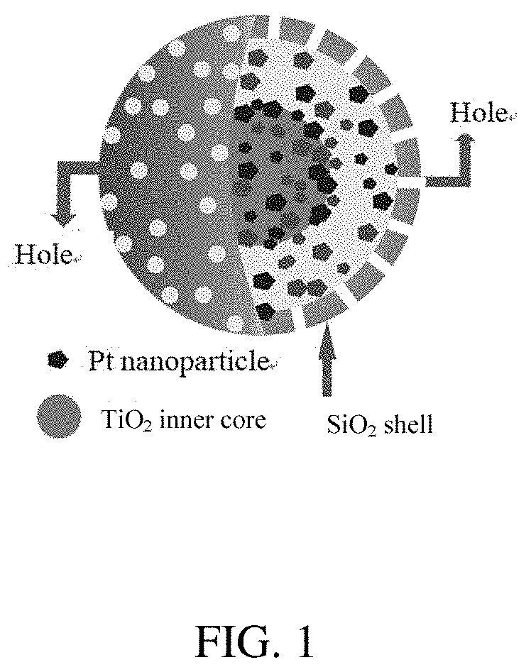
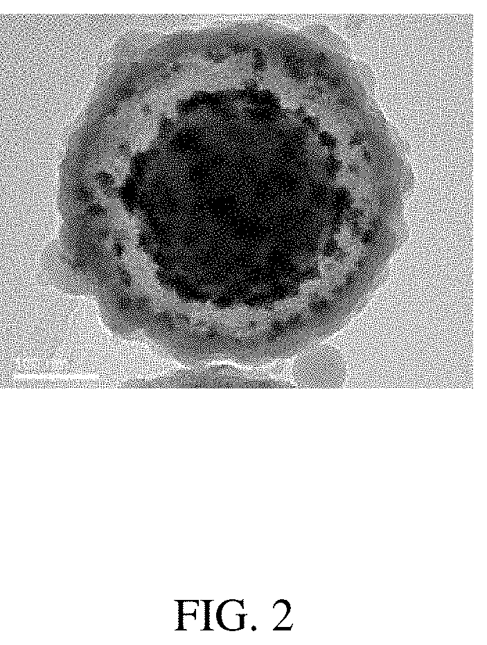
[0125]Referring to FIGS. 1 and 2, a composite photocatalyst is provided. The composite photocatalyst includes a spherical core-shell nanomotor and Pt nanodendrites dispersed in the nanomotor. And the nanomotor includes a single TiO2 inner core, a porous SiO2 shell encasing the TiO2 inner core, and a cavity between the SiO2 shell and the TiO2 inner core. The Pt nanodendrites are dispersed in the cavity. The SiO2 shell is a hollow structure and includes a plurality of holes. The diameter of the plurality of holes is about 4 nm.

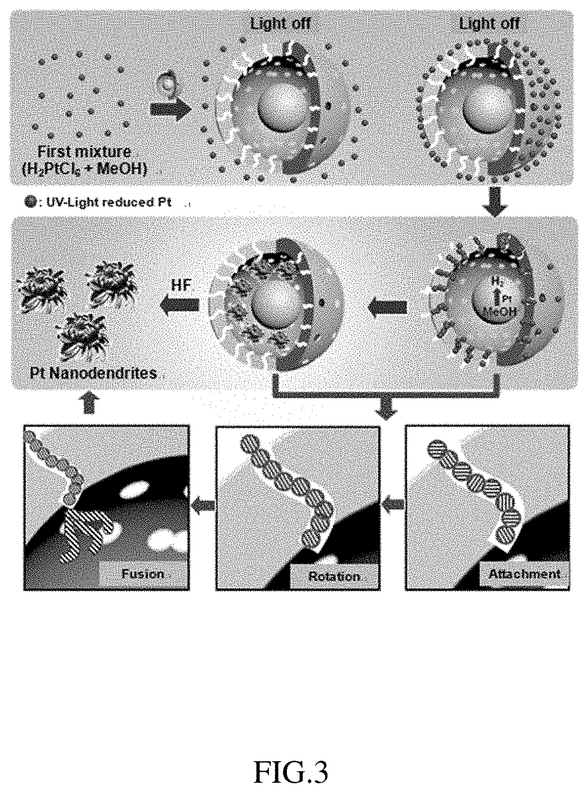
[0126]Referring to FIG. 3, a method for making the composite photocatalyst is provided. The method includes following steps:

[0127](1) preparing the nanomotor by following steps (a) to (d), as shown in FIGS. 5A and 5B:[0128](a) pretreating TiO2 nanoparticles: adding titanium dioxide nanoparticle of about 300 mg to a NaOH solution with a molar concentration of about 0.8 mol / L; after magnetic stirring treatment at about 800 round per minute for about 10 hours, and ...

embodiment 2

[0145]Referring to FIG. 10, a composite photocatalyst is provided. The composite photocatalyst includes a spherical core-shell nanomotor and Pt nanodendrites dispersed in the nanomotor. And the nanomotor includes a plurality of TiO2 inner cores, a porous SiO2 shell encasing the TiO2 inner cores, and a cavity between the SiO2 shell and the TiO2 inner cores. The Pt nanodendrites are dispersed in the cavity. The difference between the composite photocatalyst of embodiment 2 and that of embodiment 1 is that the nanomotor includes the plurality of TiO2 inner cores Pt nanodendrites.

[0146]Referrring to FIG. 11, a method for making the composite photocatalyst is provided. The method of making the composite photocatalyst of embodiment 2 is the same as the method of making the composite photocatalyst of embodiment 1, except preparing the nanomotor including the plurality of TiO2 inner cores. The method for preparing the nanomotor by following steps (a′) to (d′):

[0147](a′) pretreating TiO2 nan...

embodiment 3

[0151]A composite photocatalyst is provided. The composite photocatalyst includes a tubular core-shell nanomotor and Pd nanoparticles dispersed in the nanomotor. And the nanomotor includes a TiO2 inner core, a porous SiO2 shell encasing the TiO2 inner core, and a cavity between the SiO2 shell and the TiO2 inner core. The Pd nanoparticles are dispersed in the cavity. The difference between the composite photocatalyst of embodiment 3 and that of embodiment 1 is that the tubular core-shell nanomotor and Pd nanoparticles.

[0152]A method for making the composite photocatalyst is provided. The method of making the composite photocatalyst of embodiment 3 is the same as the method of making the composite photocatalyst of embodiment 1, except making the tubular core-shell nanomotor and Pd precursor mixture, and the Pd precursor mixture includes chloropalladic acid.


PUM

PropertyMeasurementUnit
diameteraaaaaaaaaa
diameteraaaaaaaaaa
diameteraaaaaaaaaa

Abstract

A composite photocatalyst is provided. The composite photocatalyst includes a nanomotor and a plurality of cocatalysts, the nanomotor comprises a shell formed by porous material, at least one inner core formed by a photocatalyst, and a cavity between the shell and the at least one inner core, the plurality of cocatalysts are located in the cavity. The plurality of cocatalysts are selected from the group consisting of metal nanoparticles, metal oxide nanoparticles, metal sulfide nanoparticles, phosphate nanoparticles, up-conversion material nanoparticles, and any combination thereof. A method for making the composite photocatalyst and application thereof are further provided. The plurality of cocatalysts and the nanomotor forms a photocatalytic synergistic reaction system, improving photo-catalytic activity of the composite photocatalyst.

Description

CROSS-REFERENCE TO RELATED APPLICATIONS[0001]This application claims all benefits accruing under 35 U.S.C. § 119 from China Patent Application No. 201610975568.4, filed on Nov. 7, 2016, in the State Intellectual Property Office of China, the content of which is hereby incorporated by reference. This application is a continuation-in-part under 35 U.S.C. § 120 of international patent application PCT / CN2016 / 112685, filed on Dec. 28, 2016, the content of which is also hereby incorporated by reference.FIELD OF THE DISCLOSURE[0002]The present disclosure relates to nanomotor material, and more particularly, to a composite photocatalyst.BACKGROUND OF THE DISCLOSURE[0003]Since the 19th century, advanced machines have been developed and marked as human civilization. Invention of power machines such as heat engines was the beginning of modern machine manufacturing and the great industrial revolution was arisen. Building a more complex machine at the micron or even nanometer level is the ultima...

Claims


Application Information

Patent Timeline
Patent Type & Authority Applications(United States)
IPC IPC(8): B01J35/00B01J35/02B01J35/08B01J37/34B01J27/24B01J27/125B01J27/12B01J27/051B01J23/72B01J23/52B01J23/44B01J23/42
CPCB01J27/24B01J23/42B01J27/125B01J35/08B01J37/344B01J23/44B01J23/72B01J23/52B01J35/004B01J27/051B01J35/0006B01J27/12B01J35/023C02F1/32B01J21/18C02F2305/10C02F2101/30B01J35/0013B01J35/0086B01J35/026B01J37/0018B01J37/0072B01J37/04B01J37/086B01J37/16B01J37/345B01J23/50B01J23/10B01J23/28B01J27/14B01J2523/00B01J21/063C02F2305/08C02F1/725B01J2523/36B01J2523/3775B01J2523/3787B01J2523/375B01J2523/3781B01J2523/3768B01J2523/28B01J2523/68
Inventor WANG, SHENGWANG, TAOOUYANG, SHENSHEN
Owner HANGZHOU TONG KING ENVIRONMENT TECH CO LTD
Why Eureka
Try Eureka