Eureka AIR delivers breakthrough ideas for toughest innovation challenges, trusted by R&D personnel around the world.

Structure and method of manufacturing structure

a manufacturing structure and manufacturing method technology, applied in the direction of instruments, polarising elements, projectors, etc., can solve the problem that the diffuse reflectivity did not meet the recently required level, and achieve the effect of excellent diffuse reflectivity and good diffuse reflectivity

Active Publication Date: 2019-12-26
FUJIFILM CORP
View PDF11 Cites 1 Cited by
  • Summary
  • Abstract
  • Description
  • Claims
  • Application Information

AI Technical Summary

Benefits of technology

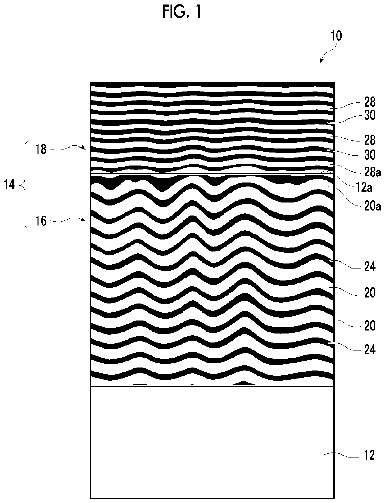
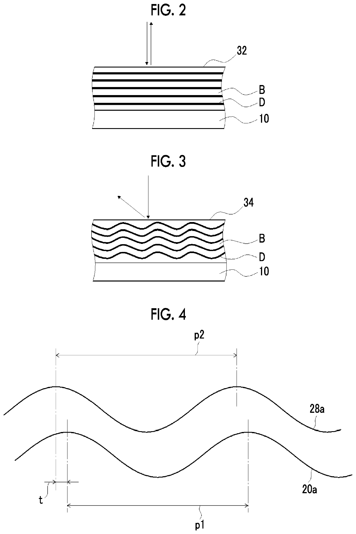
The present invention provides a structure that can reflect light in various directions (called diffuse reflectivity) using a plurality of reflection layers. This structure has excellent visibility from both normal and oblique directions. The method of manufacturing the structure is also provided. This technical effect improves the visibility of the reflected light and enhances the quality of the reflected image.

Problems solved by technology

As a result, the diffuse reflectivity did not satisfy a recently required level and therefore a further improvement was necessary.

Method used


Image

  • Structure and method of manufacturing structure
  • Structure and method of manufacturing structure
  • Structure and method of manufacturing structure

Examples


example 1

[0300]As the substrate 12, a poly-ethylene terephthalate (PET) substrate (manufactured by Toyobo Co., Ltd.) subjected to a rubbing treatment was prepared.

[0301]A liquid crystal composition 1 was applied to the surface of the substrate 12 subjected to the rubbing treatment as the first layer composition at room temperature using a wire bar. The coated layer of the liquid crystal composition was dried at room temperature for 50 seconds and then heated in an atmosphere at 95° C. for 1 minute to align the liquid crystal compound.

[0302]Thereafter, the coated layer was irradiated with the ultraviolet (UV) rays using a D bulb (lamp, 90 mW / cm2) manufactured by Fusion UV Systems, Inc. at an output of 80% at 30° C. for 8 seconds, so that the first reflection layer 16 was formed on the substrate 12. In the above procedure, after aligning the liquid crystal compound at 95° C., the liquid crystal composition was cooled to 30° C. A part of the formed first reflection layer 16 was peeled off, and ...


PUM

PropertyMeasurementUnit
selective reflection wavelengthaaaaaaaaaa
wavelength rangeaaaaaaaaaa

Abstract

An object of the present invention is to provide a structure having an excellent diffuse reflectivity and a method of manufacturing a structure. The object is achieved by a structure including a plurality of reflection layers formed by fixing a cholesteric liquid crystalline phase, the reflection layers being laminated, in which in a reflection layer, a bright portion and a dark portion derived from the cholesteric liquid crystalline phase have wavy structures in a cross section, and undulations of the wavy structures of bright portions closest to each other coincide in the adjacent reflection layers; and by a method of manufacturing a structure including forming a reflection layer formed by fixing a cholesteric liquid crystalline phase, in which a bright portion and a dark portion have wavy structures, in a cross section, and forming the reflection layer on a first reflection layer by a coating method using an composition containing a liquid crystal compound and a chiral agent.

Description

CROSS-REFERENCE TO RELATED APPLICATIONS[0001]This application is a Continuation of PCT International Application No. PCT / JP2018 / 007747 filed on Mar. 1, 2018, which claims priority under 35 U.S.C. § 119(a) to Japanese Patent Application No. 2017-039413 filed on Mar. 2, 2017. The above application is hereby expressly incorporated by reference, in its entirety, into the present application.BACKGROUND OF THE INVENTION1. Field of the Invention[0002]The present invention relates to a structure in which a reflection layer is laminated, and a method of manufacturing the structure.2. Description of the Related Art[0003]A layer formed by fixing a cholesteric liquid crystalline phase is known as a layer having a property of selectively reflecting either right circular polarization light or left circular polarization light in a specific wavelength range. For this reason, it has been developed for various applications, for example, it is used as a phase difference layer (JP2005-049866A). Further...

Claims


Application Information

Patent Timeline
Patent Type & Authority Applications(United States)
IPC IPC(8): G03B21/604B32B7/023G02F1/1335G02B5/26G02B5/30
CPCG02B5/26G02F1/133536G03B21/604G02B5/3033G02B5/3066B32B7/023G02B5/208G02B5/3016G02B5/30
Inventor KATOH, SHUNYATAKASAGO, RIE
Owner FUJIFILM CORP
Why Eureka
Eureka Blog
Learn More