Method of manufacturing epitaxial silicon wafers

a technology of epitaxial film and silicon wafer, which is applied in the direction of crystal growth process, polycrystalline material growth, chemically reactive gas growth, etc., can solve the problems of increasing the carbon concentration in the epitaxial film, failing to consider the balance of the gases flowing above and below the susceptor, etc., and achieves the effect of reducing the carbon concentration

Active Publication Date: 2019-12-26
GLOBALWAFERS JAPAN
View PDF0 Cites 0 Cited by
  • Summary
  • Abstract
  • Description
  • Claims
  • Application Information

AI Technical Summary

Benefits of technology

[0016]By controlling the flow rate ratio of the flow rate of the purging gas flowing in the lower space of the reaction chamber to the flow rate of the processing gas flowing in the upper space thereof, this configuration enables to suppress swirling up of an atmospheric gas containing carbon component and to reduce carbon concentration in the epitaxial films.

Problems solved by technology

The gas-phase grown method disclosed in JP-A-2007-326761, however, fails to consider balancing of the gases flowing above the susceptor and below the susceptor.
As a result, there arises a problem of increasing carbon concentration in the epitaxial film formed on the wafer W.

Method used


Image

  • Method of manufacturing epitaxial silicon wafers
  • Method of manufacturing epitaxial silicon wafers
  • Method of manufacturing epitaxial silicon wafers

Examples


experiment 1

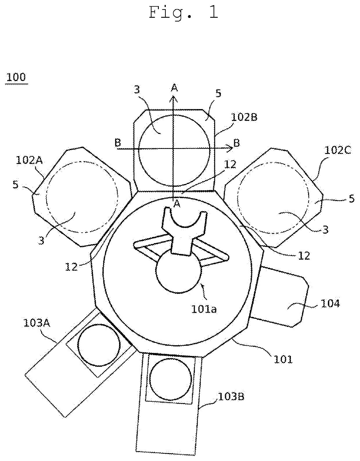
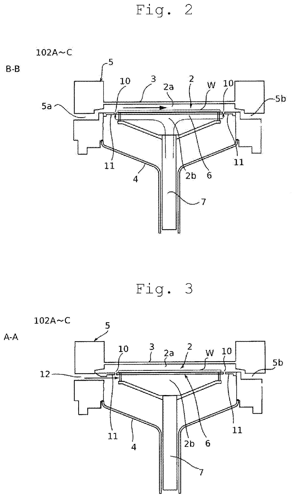
[0050]In Experiment 1, three evaluation items, specifically metal contamination in the chamber, swirling up of an atmospheric gas containing carbon component, and turbulence of the processing gas, were evaluated by experiments, in order to define preferable ranges of the following issues, using a CVD apparatus the configuration of which is shown in FIGS. 1 through 3:[0051]1. Ratio of the flow rate of the main purging gas in a lower space to the flow rate, set as 100, of the processing gas in the upper space,[0052]2. Pressure in the chamber,[0053]3. Susceptor height with respect to the height of the preheat ring, and[0054]4. Ratio of the flow rate of the main purging gas and the slit purge gas in the lower space to the flow rate, set as 100, of the processing gas in the upper space.

Specific evaluation items are following three points: metal contamination in the chamber, swirling up of carbon containing atmosphere and turbulence of the processing gas.

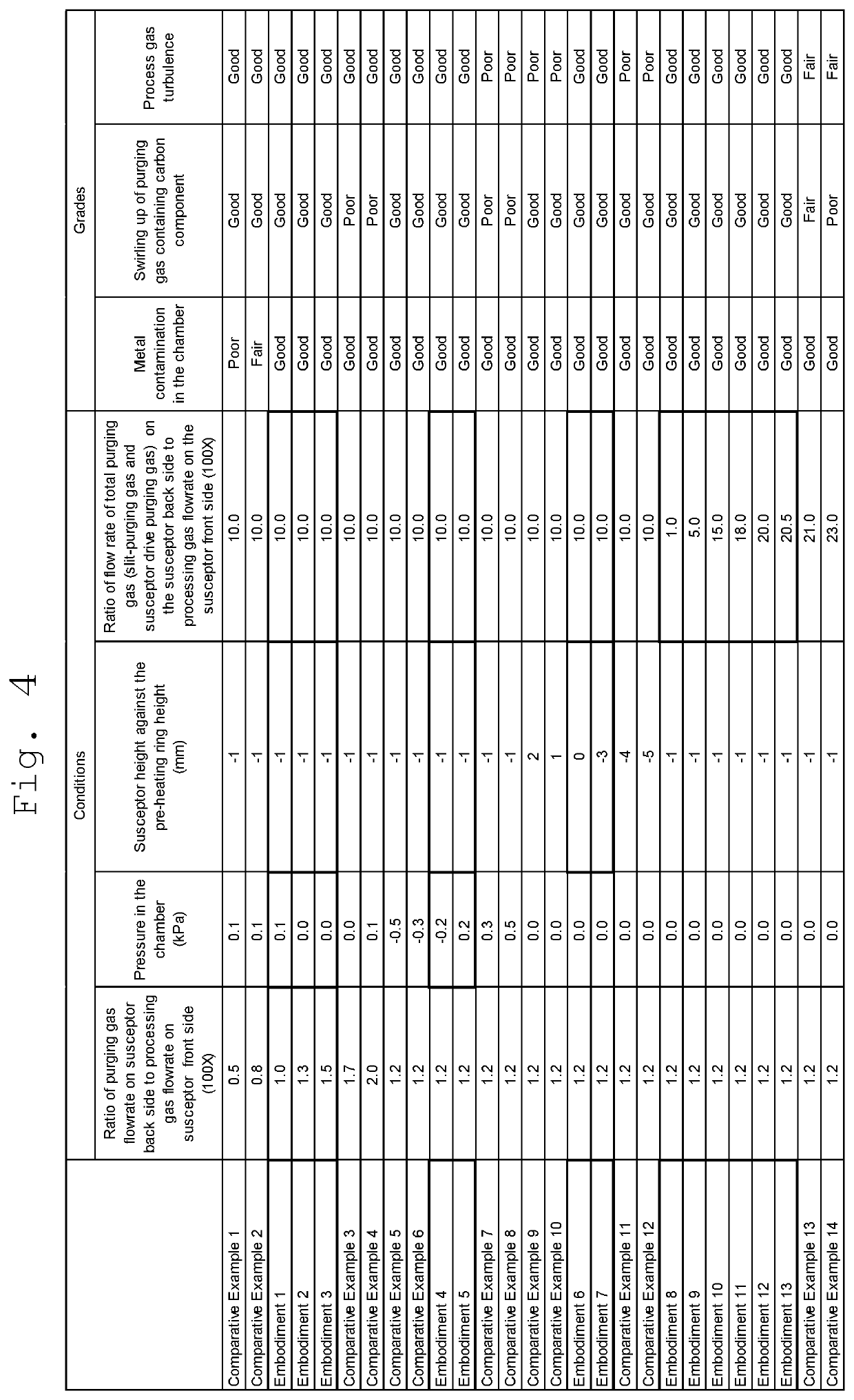
[0055]Table of FIG. 3 shows condit...

experiment 2

[0061]In Experiment 2, under the favorable condition defined by the results of Experiment 1, carbon concentration contained in the epitaxial films against the flow rate of purging gas in the lower space of the chamber is evaluated using photoluminescence (PL) measurement method.

[0062]In Embodiment 14, the ratio of the flow rate of the main purging gas in a lower space to the flow rate, set as 100, of the processing gas in the upper space was set to be 1.25 / 100 with a flow rate of 0.5 slm. The pressure in the chamber was set to be in a range of the atmospheric pressure ±0.2 kPa and the susceptor height with respect to the height of the preheat ring was set to be in a range of −3 mm to 0 mm. Under the above-stated condition, epitaxial films were formed on wafers and carbon intensity was measured with the PL measurement method.

[0063]In Comparative example 15, the ratio of the flow rate of the main purging gas in a lower space to the flow rate, set as 100, of the processing gas in the u...


PUM

PropertyMeasurementUnit
atmospheric pressureaaaaaaaaaa
heightaaaaaaaaaa
pressureaaaaaaaaaa

Abstract

A method for manufacturing an epitaxial silicon wafer enables to lower carbon concentration in an epitaxial film. The method forming an epitaxial silicon wafer where an epitaxial film is formed on a silicon wafer in a reaction chamber including a wafer-holding susceptor that separates an upper and lower space communicating through a predetermined gap includes steps of forming a flow of a processing gas flowing laterally along an upper surface of the wafer in the upper space and a flow of a main purging gas flowing towards the susceptor upwardly in the lower space being formed simultaneously, setting a flow rate ratio of the main purging gas flow rate to the processing gas flow rate to be 1.0/100 to 1.5/100 where the processing gas flow rate is set as 100, and controlling a pressure in the upper space to be within an atmospheric pressure ±0.2 kPa at least.

Description

BACKGROUND OF THE INVENTIONField of the Invention[0001]The present invention relates to methods of manufacturing epitaxial silicon wafers, particularly to a method of manufacturing an epitaxial wafer allowing reduction of carbon concentration (measurement intensity) in a grown epitaxial film.Description of the Related Art[0002]For devices based on an insulated gate bipolar transistor (IGBT), utilizing both electrons and holes as carriers, for example, highly required is lowering concentration of carbon in epitaxial films. Namely, suppression of intake of carbon component into epitaxial films is one of the most crucial requirements in epitaxial silicon wafer manufacturing.[0003]One of the reasons for the high concentration of carbon in the epitaxial film can be attributed to a fact that carbon component contained in the processing gas contacting with members in a chamber is taken into the epitaxial film during growing.[0004]Another reason is thought that purging gas flowing under the...

Claims


Application Information

Patent Timeline
Patent Type & Authority Applications(United States)
IPC IPC(8): H01L21/02H01L21/687
CPCH01L21/0262H01L21/68714H01L21/02381C23C16/455C23C16/4582C23C16/24C30B29/06C30B25/14C23C16/45521H01L21/02271H01L21/02002H01L21/02293H01L21/02115H01L21/67017H01L21/67098H01L21/68721
Inventor YAMAMOTO, JUNMATSUDA, SHINYA
Owner GLOBALWAFERS JAPAN
Why Eureka
Try Eureka