Supercharge Your Innovation With Domain-Expert AI Agents!

Method for manufacturing conductive plug

a technology of conductive plugs and manufacturing methods, which is applied in the direction of semiconductor devices, electrical equipment, transistors, etc., can solve problems such as affecting the on-resistance of circuits

Inactive Publication Date: 2019-12-26
SILERGY SEMICON TECH (HANGZHOU) CO LTD
View PDF7 Cites 1 Cited by
  • Summary
  • Abstract
  • Description
  • Claims
  • Application Information

AI Technical Summary

Benefits of technology

The patent describes a technique for creating a flat surface on a semiconductor wafer by depositing a thin film of material over an existing pattern. This technique helps to create smaller and more dense components. The process involves polishing the surface of the wafer with a combination of abrasive material and corrosive chemicals to remove any irregular topography and create a smooth, even surface.

Problems solved by technology

Also, the interconnect resistance of subsequent processes can affect the on-resistance of the circuit.

Method used


Image

  • Method for manufacturing conductive plug
  • Method for manufacturing conductive plug
  • Method for manufacturing conductive plug

Examples


Embodiment Construction

[0006]Reference may now be made in detail to particular embodiments of the invention, examples of which are illustrated in the accompanying drawings. While the invention may be described in conjunction with the preferred embodiments, it may be understood that they are not intended to limit the invention to these embodiments. On the contrary, the invention is intended to cover alternatives, modifications and equivalents that may be included within the spirit and scope of the invention as defined by the appended claims. Furthermore, in the following detailed description of the present invention, numerous specific details are set forth in order to provide a thorough understanding of the present invention. However, it may be readily apparent to one skilled in the art that the present invention may be practiced without these specific details. In other instances, well-known methods, procedures, processes, components, structures, and circuits have not been described in detail so as not to ...


PUM


Abstract

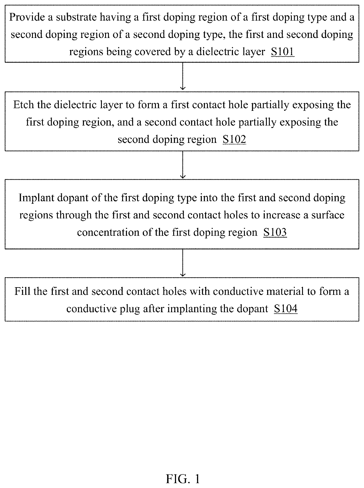
A method can include: providing a substrate comprising a first doping region of a first doping type, and a second doping region of a second doping type, where the first and second doping regions are covered by a dielectric layer; etching the dielectric layer to form a first contact hole partially exposing the first doping region, and a second contact hole partially exposing the second doping region; implanting dopant of the first doping type into the first and second doping regions through the first and second contact holes to increase a surface concentration of the first doping region; and after implanting the dopant, filling the first and second contact holes with conductive material to form conductive plugs.

Description

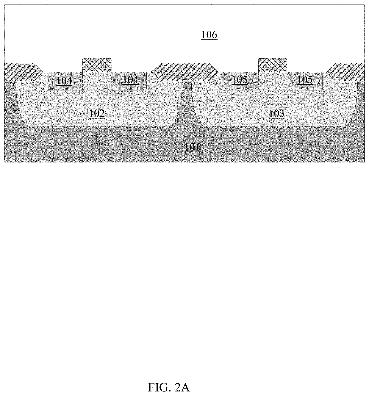
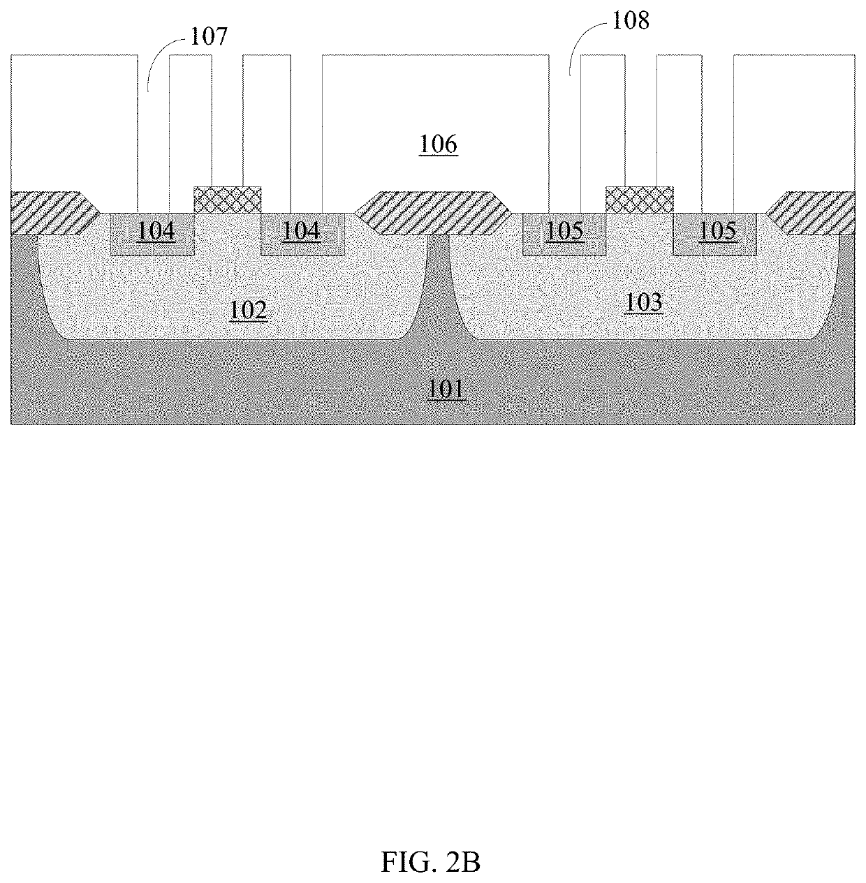
RELATED APPLICATIONS[0001]This application claims the benefit of Chinese Patent Application No. 201810635997.6, filed on Jun. 20, 2018, which is incorporated herein by reference in its entirety.FIELD OF THE INVENTION[0002]The present invention generally relates to semiconductor devices and processes, and more particularly to methods of manufacturing conductive plugs.BACKGROUND[0003]The on-resistance of a circuit may be substantially affected by intrinsic on-resistance and interconnection resistance of the device. After the device has been designed and previous processes have been completed, the value of the intrinsic on-resistance of the device has been determined. Also, the interconnect resistance of subsequent processes can affect the on-resistance of the circuit. Among these factors, the resistivity of the metal is relatively low, and the on-resistance of the circuit can be most affected by the resistance of the contact hole.BRIEF DESCRIPTION OF THE DRAWINGS[0004]FIG. 1 is a flow...

Claims


Application Information

Patent Timeline
Patent Type & Authority Applications(United States)
IPC IPC(8): H01L21/266H01L21/768H01L29/417H01L29/08
CPCH01L29/0847H01L29/41725H01L21/76802H01L21/266H01L21/76877H01L21/76838H01L21/76814H01L21/823814H01L21/823871H01L27/092H01L29/456H01L29/66568
Inventor WANG, HUAN
Owner SILERGY SEMICON TECH (HANGZHOU) CO LTD
Features
  • R&D
  • Intellectual Property
  • Life Sciences
  • Materials
  • Tech Scout
  • Unparalleled Data Quality
  • Higher Quality Content
  • 60% Fewer Hallucinations
Learn More