A step-by-step phosphorus doping method for high-efficiency and low-cost crystalline silicon batteries

A low-cost technology for crystalline silicon cells, applied in circuits, photovoltaic power generation, electrical components, etc., can solve problems such as difficult to achieve control accuracy of high-efficiency crystalline silicon cells, and achieve high open circuit voltage, low recombination current, and low doping concentration Effect

Active Publication Date: 2019-01-08
CHANGZHOU UNIV +1
View PDF6 Cites 13 Cited by
  • Summary
  • Abstract
  • Description
  • Claims
  • Application Information

AI Technical Summary

Problems solved by technology

Existing methods are difficult to achieve the control accuracy of phosphorus lateral a

Method used


Image

  • A step-by-step phosphorus doping method for high-efficiency and low-cost crystalline silicon batteries
  • A step-by-step phosphorus doping method for high-efficiency and low-cost crystalline silicon batteries
  • A step-by-step phosphorus doping method for high-efficiency and low-cost crystalline silicon batteries

Examples


Embodiment 1

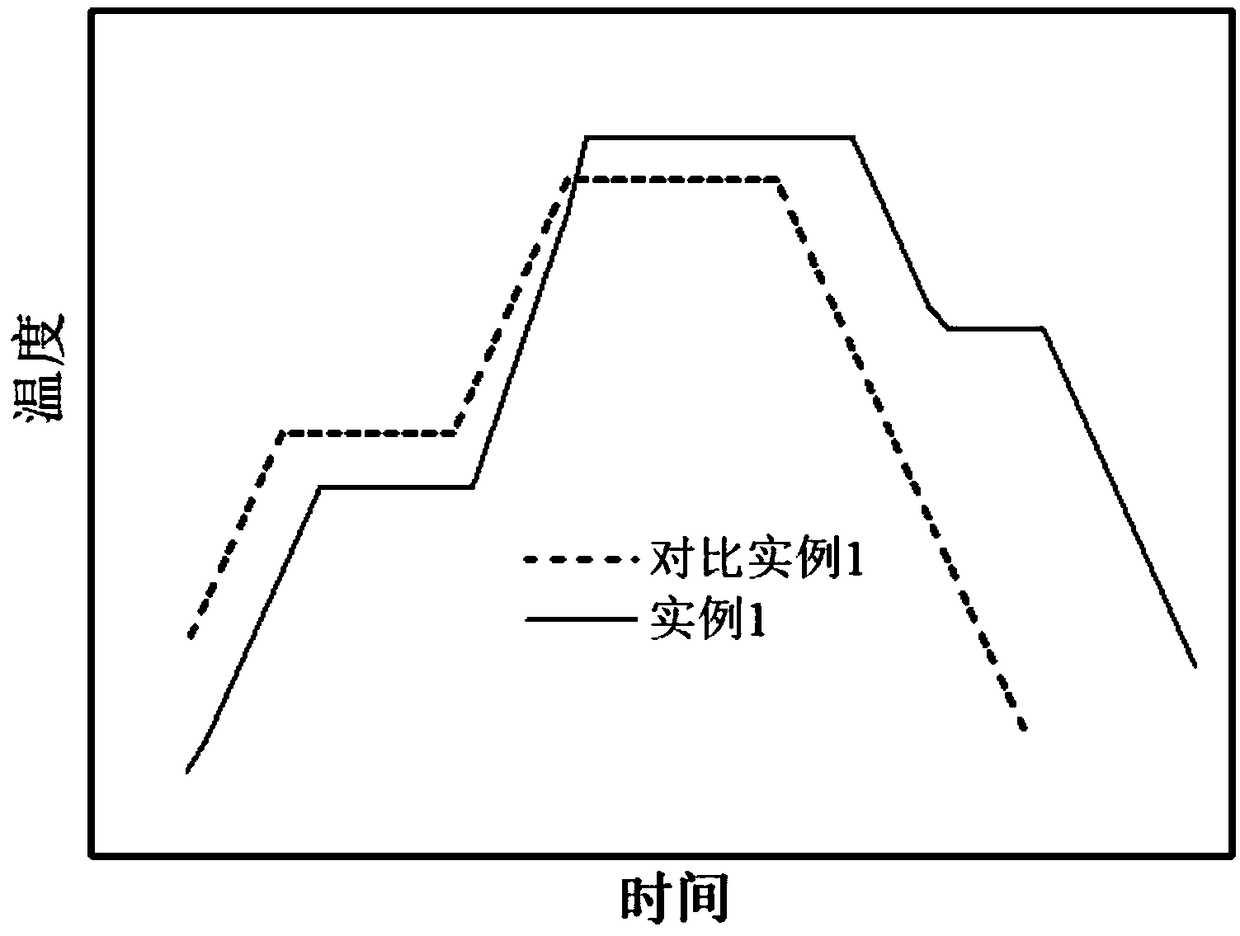
[0027] The primary depletion-type phosphorus diffusion of high-efficiency and low-cost crystalline silicon cells is combined with the secondary high-concentration shallow layer diffusion and back-etching phosphorus doping methods, and the following steps are carried out:

[0028] Step 1, the first low-temperature deposition, the temperature is controlled at 785°C, the nitrogen flow rate is 13slm, the oxygen flow rate is 250sccm, the phosphorus oxychloride flow rate is 500sccm, and the deposition is 5min;

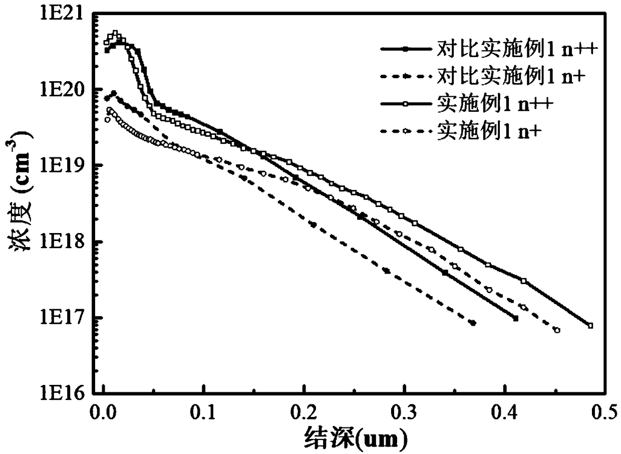
[0029] Step 2. Keep the nitrogen flow rate at 13slm, the oxygen flow rate at 1000sccm, stop the phosphorus oxychloride flow rate, raise the temperature to 860°C at a heating rate of 10°C / min, and maintain the first push for 40min to form a low surface concentration layer n+; surface concentration 5.43×10 19 / cm 3 ;

[0030] Step 3. Keep the nitrogen flow rate at 13slm, stop the oxygen flow rate, and cool down to 830°C at a cooling rate of 10°C / min. After the second depositio...

Embodiment 2

[0036] Step 1, the first low-temperature deposition, the temperature is controlled at 760°C, the nitrogen flow rate is 11slm, the oxygen flow rate is 200sccm, the phosphorus oxychloride flow rate is 400sccm, and the deposition is 10min;

[0037] Step 2. Keep the nitrogen flow rate at 11slm, the oxygen flow rate at 800sccm, stop the phosphorus oxychloride flow rate, raise the temperature to 900°C at a heating rate of 10°C / min, and maintain the first advance for 45min to form a low surface concentration layer n+;

[0038] Step 3. Keep the nitrogen flow rate at 11slm, stop the oxygen flow rate, and cool down to 820°C at a cooling rate of 10°C / min. After the second deposition, the nitrogen flow rate is controlled at 11slm, the oxygen flow rate is controlled at 300sccm, and the phosphorus oxychloride flow rate is Control at 600sccm, deposit for 25min;

[0039] Step 4. Keep the nitrogen flow at 11slm, the oxygen flow at 850sccm, stop the flow of phosphorus oxychloride, maintain the ...

Embodiment 3

[0044] Step 1, the first low-temperature deposition, the temperature is controlled at 800°C, the nitrogen flow rate is 15slm, the oxygen flow rate is 280sccm, the phosphorus oxychloride flow rate is 560sccm, and the deposition is 3min;

[0045] Step 2. Keep the nitrogen flow rate at 15slm, the oxygen flow rate at 1100sccm, stop the phosphorus oxychloride flow rate, raise the temperature to 850°C at a heating rate of 10°C / min, and maintain the first advance for 30min to form a low surface concentration layer n+;

[0046] Step 3. Keep the nitrogen flow at 15slm, stop the oxygen flow, and cool down to 810°C at a cooling rate of 10°C / min. After the second deposition, control the nitrogen flow at 15slm, the oxygen flow at 450sccm, and the phosphorus oxychloride flow rate Control at 850sccm, deposit for 15 minutes;

[0047] Step 4. Keep the nitrogen flow at 15slm, the oxygen flow at 1150sccm, stop the flow of phosphorus oxychloride, maintain the temperature at 810°C, and carry out t...


PUM

PropertyMeasurementUnit
Surface concentrationaaaaaaaaaa

Abstract

The invention belongs to the technical field of solar cell manufacturing, and relates to a step-by-step phosphorus doping method of a high-efficiency and low-cost crystal silicon cell, namely a primary depletion diffusion combined with secondary high-concentration shallow layer diffusion and back etching method. By controlling the flow of oxygen, A low-temperature low-phosphorus source depositionis carry out for that first time on a p-type silicon substrate by nitrogen flow rate and phosphorus oxychloride flow rate, After a long time of high temperature propulsion, the phosphorus in the phosphor-silicate glass is exhausted, and the low surface concentration layer n + is realized. The second time, the phosphor-free glass is deposited on the phosphor-silicate glass, and the high surface concentration layer n + + is pushed to form a very thin high concentration layer, which can be quickly etched off by means of back etching. The method can accurately control the phosphorus doping distribution in different regions independently to ensure that the non-electrode region has low doping concentration and low recombination current so as to ensure higher open-circuit voltage. The electrode region has high doping concentration, which forms good ohmic contact with the metal electrode and ensures that the filling factor is not lost, so as to improve the photoelectric conversion performanceof the battery as a whole.

Description

technical field [0001] The invention belongs to the technical field of solar cell manufacturing, and in particular relates to a step-by-step phosphorus doping method for high-efficiency and low-cost crystalline silicon cells, that is, a primary depletion-type phosphorus diffusion combined with a secondary high-concentration shallow layer diffusion and back-etching method. Background technique [0002] Photovoltaic power generation is one of the fastest growing renewable energy technologies in recent years, and crystalline silicon solar cells account for more than 90% of the global photovoltaic market. High photoelectric conversion efficiency and low battery manufacturing cost are the eternal themes for the development of photovoltaic industry. High-efficiency crystalline silicon solar cells mainly integrate advanced doping technology, surface passivation technology, light trapping technology, electrode manufacturing technology, etc. High-efficiency crystalline silicon solar...

Claims


Application Information

Patent Timeline
IPC IPC(8): H01L21/223H01L21/324H01L31/18
CPCH01L21/223H01L21/324H01L31/1804H01L31/0224H01L31/068Y02E10/547Y02P70/50
Inventor 丁建宁叶枫袁宁一
Owner CHANGZHOU UNIV
Why Eureka
Try Eureka