
Chemical vapor deposition rate prediction method

A technology of chemical vapor deposition and prediction method, which is applied in the field of chemical vapor deposition rate prediction, and can solve the problems of poor model universality and large error.

Active Publication Date: 2019-12-20
SOUTH CHINA UNIV OF TECH
View PDF6 Cites 11 Cited by
  • Summary
  • Abstract
  • Description
  • Claims
  • Application Information

AI Technical Summary

Problems solved by technology

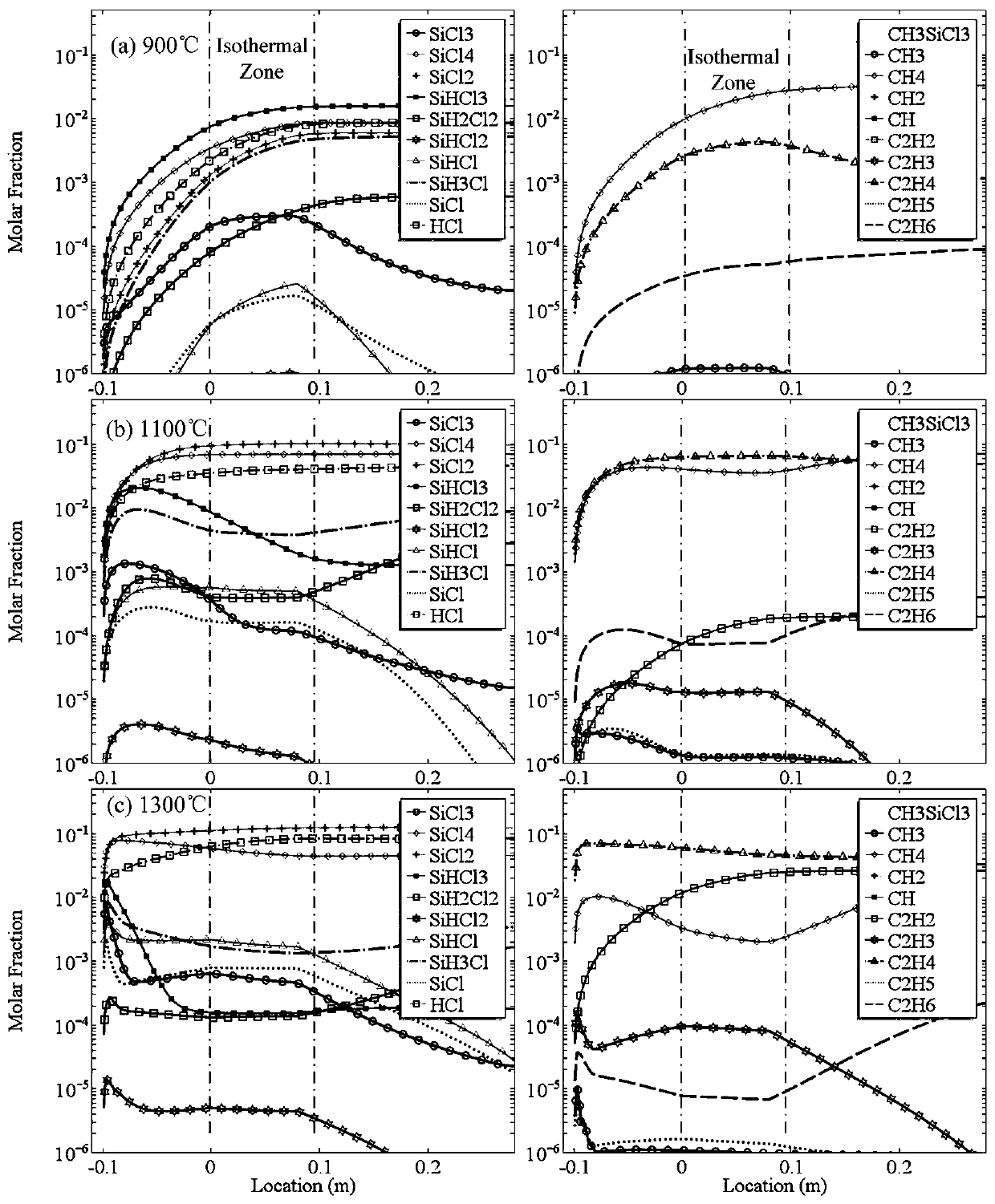
[0007] 1. Before the gas-phase substances reach the surface of the deposition substrate, the precursor will generate a large amount of mesophase substances. It is difficult to accurately judge which mesophases are the main contributors to the deposited solid phase and which mesophases control the deposition rate only by the concentration of the gas-phase components. The main factors lead to the selection of the mesophase is very empirical and has a large error;
[0008] 2. Even if the main mesophase is determined, because various mesophases compete to occupy surface vacancies during the deposition process, and these relationships may change with changes in temperature, pressure and the concentration of each component, only relying on the existing It is difficult to determine the influence of these factors on the viscosity coefficients of various main mesophases by technology, and the viscosity coefficients currently used are mostly measured under non-sedimentary conditions. It is doubtful whether it can be directly applied to the actual depositional environment. This is also one of the reasons for the poor universality of the established model

Method used


Image

  • Chemical vapor deposition rate prediction method
  • Chemical vapor deposition rate prediction method
  • Chemical vapor deposition rate prediction method

Examples


Embodiment Construction

[0070] The following will clearly and completely describe the technical solutions in the embodiments of the present invention with reference to the accompanying drawings in the embodiments of the present invention. Obviously, the described embodiments are only part of the embodiments of the present invention, not all of them. Based on the embodiments of the present invention, all other embodiments obtained by persons of ordinary skill in the art without making creative efforts belong to the protection scope of the present invention.

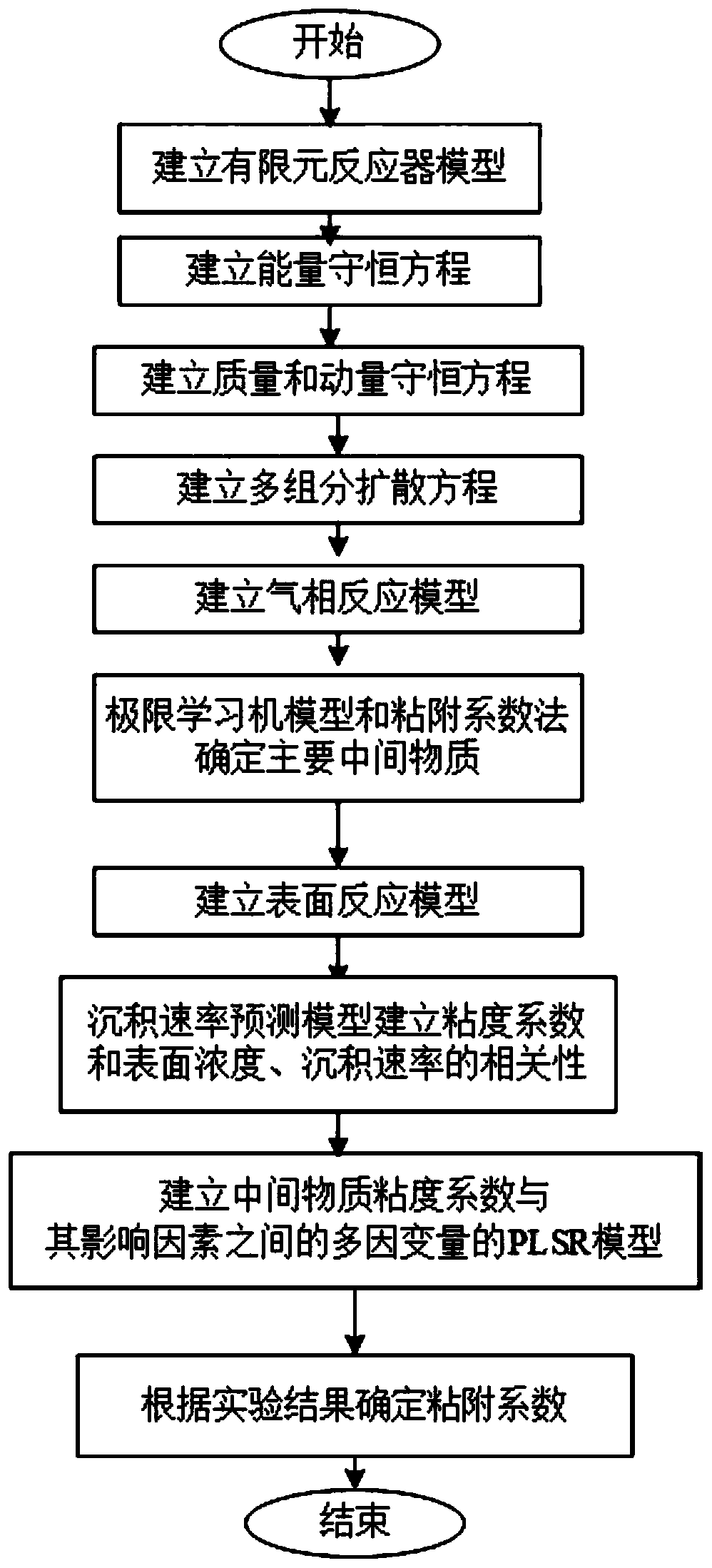
[0071] according to figure 1 A chemical vapor deposition rate prediction method is shown, and the specific prediction method is as follows:

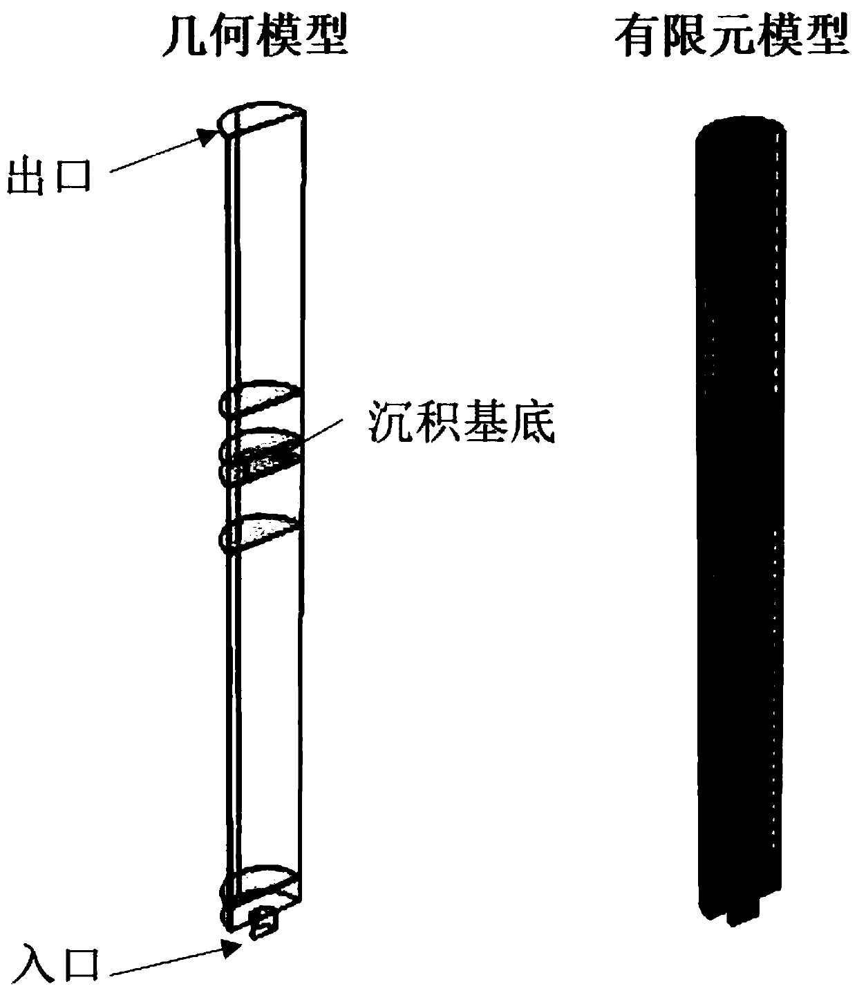
[0072] S1. Establish a finite element reactor model: simulate the reactor as a three-dimensional cylinder model according to the experimental conditions, then cut and divide the reactor into reactor cavity, air inlet and deposition base, and cut the cylinder in order to reduce the amount of calculation, on...


PUM


Abstract

The invention discloses a chemical vapor deposition rate prediction method, and particularly relates to the field of chemical process research. The chemical vapor deposition rate prediction method comprises the following steps: building a finite element reactor model; establishing an energy conservation equation; establishing a mass conservation equation and a momentum conservation equation; establishing a multi-component diffusion equation; establishing a gas phase reaction model; determining main intermediate substances by an extreme learning machine model and an adhesion coefficient method;establishing a surface reaction model; establishing correlation between the viscosity coefficient and the surface concentration as well as the deposition rate by the deposition rate prediction model;establishing a multi-dependent-variable PLSR model between the viscosity coefficient of the intermediate substance and the influence factor of the intermediate substance; and determining an adhesioncoefficient according to an experimental result. According to the chemical vapor deposition rate prediction method, the simulation technology of machine learning and computational fluid mechanics is combined, and the dependence of model parameters on human experience is greatly reduced, and the important mesophase and the viscosity coefficient can be accurately determined through a small number ofexperiments, and the technical effects of high prediction result accuracy and high reliability are achieved.

Description

technical field [0001] The invention relates to the technical field of chemical process research, and more specifically, the invention relates to a method for predicting chemical vapor deposition rate. Background technique [0002] Ceramic matrix composites are a type of composite materials that use ceramics as a matrix and various fibers. The ceramic matrix can be high-temperature structural ceramics such as silicon nitride and silicon carbide. It retains the excellent properties of ceramic materials such as high temperature resistance, low density, high specific strength and oxidation resistance, and overcomes the fatal weaknesses of ceramic materials such as high brittleness and poor reliability. As a high-temperature structural material, it can be used in certain high-temperature and harsh environments. Known as "new materials facing the 21st century", it has received more and more attention. [0003] At present, chemical vapor deposition (CVD) is the main method for pr...

Claims


Application Information

Patent Timeline
Patent Type & Authority Applications(China)
IPC IPC(8): G06F17/50G16C20/30G16C20/70
CPCG16C20/30G16C20/70
Inventor 关康卢振亚吴建青曾庆丰冯志强刘建涛高勇龚振远
Owner SOUTH CHINA UNIV OF TECH
Learn More