

Superelastic bone compression staple in staple system
- Summary
- Abstract
- Description
- Claims
- Application Information
AI Technical Summary
Benefits of technology
Problems solved by technology
Method used
Image

Examples
second embodiment
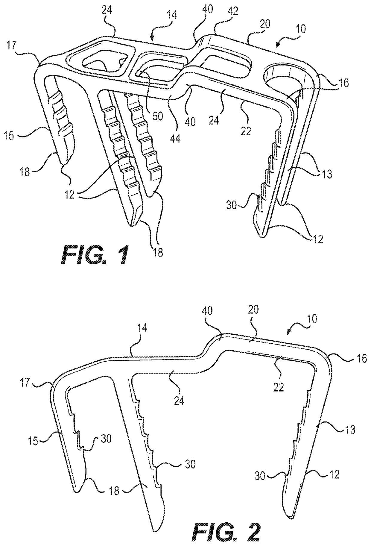
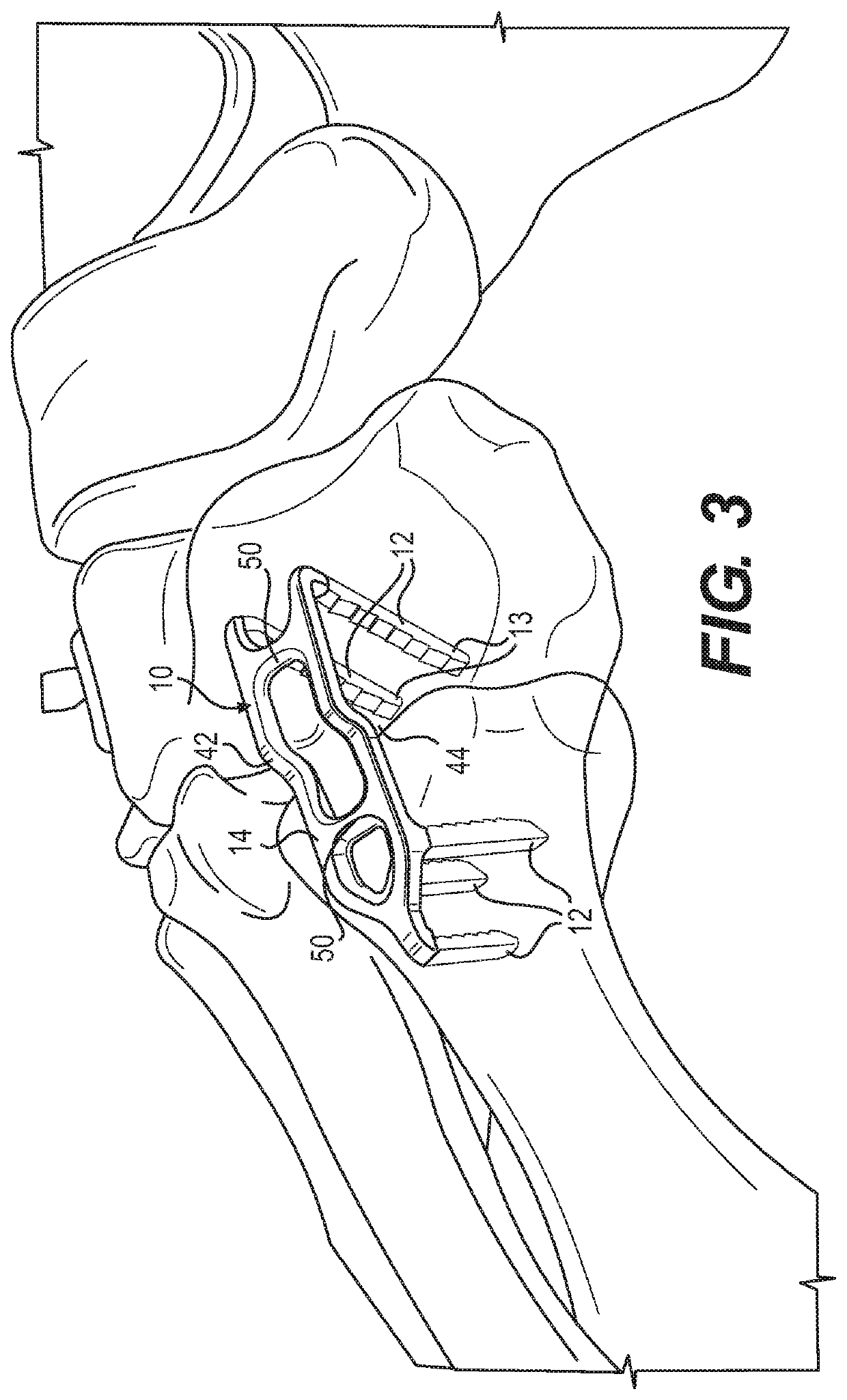
[0039]The bridge member 14 further includes an offset area 40 which includes a first bend 42 roughly transverse to the length of the bridge member in the through or z direction, and spaced from that a second bend 44 which returns the bridge member to the first direction so as to form two parallel segments 46, 48. The offset area further includes an opening 50 which is sized and configured to accommodate a secondary staple fully within the opening to apply an additional compressive force below the opening to bone segments, and by “accommodate,” it is meant for both the first and the second embodiment that the primary and the secondary staple bridges interface or interact so as to minimize any additional and extraneous material relative to the bone. Thus, the invention is designed for use in areas where the bone is close to the skin, and there may be little soft tissue to cover the implant.
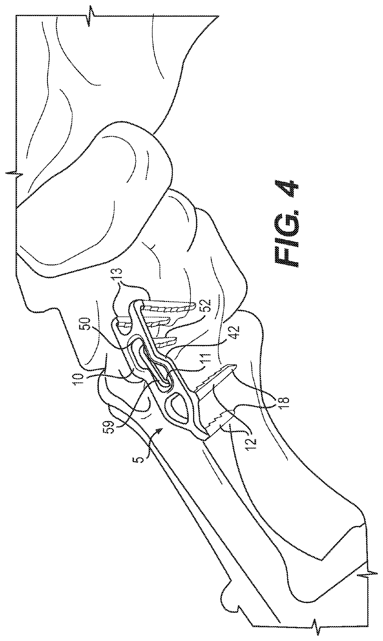
[0040]The secondary staple 11 forms a part of the staple system, and comprises a pair of legs 52...
first embodiment
[0049]The secondary staple 111 forms a second part of the staple system, and comprises a one or two legs 158 joined at either end to a bridge member 159 having a central elongated diamond shaped opening 162 to increase the volume of the material at the shoulder junction. The legs extend transverse to the long axis of the bridge member in an activated state for insertion within the opening of the primary staple and after insertion they apply an inward force along the direction of the axis of that bridge member. As in the first embodiment, staple legs can have an unusual and complex shape. While this can be a rectangle, they can form other polygons in cross section, such as pentagons. The legs may also include features 30 to help hold the legs in the bone, such as texturing, or ridges or barbs that help to hold the legs in position. Preferably, the surfaces of the legs that include this feature are opposing surfaces, such as surfaces that face an opposing leg.
PUM
 Abstract
Description
Claims
Application Information