Telemetric tibial tray

Active Publication Date: 2005-01-13
DEPUY PROD INC
View PDF58 Cites 188 Cited by
  • Summary
  • Abstract
  • Description
  • Claims
  • Application Information

AI Technical Summary

Benefits of technology

[0022] In another feature of the invention, the no-load post is eliminated so that the cavity-side face of the load diaphragm is featureless. Removing the no-load posts eliminates stress risers at the junction between the no-load posts and the diaphragms and significantly reduces the risk of fracture at the base of the support posts.
[0023] In addition, removing the no-load posts allows repositioning of the strain gage array from the pattern employed in the prior art. It has been found that the radial strain pattern across the load diaphragm exhibits significant micro-strain behavior at the center of the diaphragm. Removing the no-load posts allows placement of the radially inboard strain gages as close to the center of the diaphragm as possible. At each circumferential position, there is more room for the radially outermost strain gage so that the two strain gages at each circumferential position yield a more accurate differential strain reading, which translates into a more accurate measure of the diaphragm strain.
[0024] The radial position of the inner and outer strain gages is also calibrated according to the micro-strain response of the transducer cavity diaphragm to load. In one aspect of the invention, the inner strain gage is positioned to span the radial location at which the maximum positive micro-strain occurs. The outer strain gage is positioned at a radial location between the zero crossing point and the outer wall of the cylindrical transducer cavity. In a more specific aspect, the outer strain gage is positioned to span the radial location of the maximum negative micro-strain response of the diaphragm. These optimized locations produce the g

Problems solved by technology

Joint replacement surgery is quite common and enables many individuals to function normally when otherwise it would not be possible to do so.
Natural friction within a replaced, artificial joint can lead to the development of wear debris in which minute particles of debris (e.g., metal or plastic from the prosthesis) become dislodged and migrate within the joint.
The phenomenon of wear debris within artificial joints is a serious problem that can inhibit the proper mechanical functioning of the joint.
Moreover, wear debris can lead to osteolysis and bone deterioration.
The tibial bearing member is typically made of an ultrahigh molecular weight polyethylene (UHMWPE), and friction, continuous cycling and stress can cause some erosion and/or fracture of the tibial bearing member, thus leading to wear debris.
The risk of wear debris can be even greater during malalignment of an artificial knee joint, which can result from normal usage or from imperfect and/or inaccurate implantation of the prosthesis within a patient.
This uneven distribution of load (or edge loading) can accelerate the development of wear debris.
Contact stresses on the tibial bearing member increase substantially with malalig

Method used


Image

  • Telemetric tibial tray
  • Telemetric tibial tray
  • Telemetric tibial tray

Examples


Example

[0034] For the purpose of promoting an understanding of the principles of the invention, reference will now be made to the embodiments illustrated in the drawings and described in the following written specification. It is understood that no limitation to the scope of the invention is thereby intended. It is further understood that the present invention includes any alterations and modifications to the illustrated embodiments and includes further applications of the principles of the invention as would normally occur to one skilled in the art to which this invention pertains.

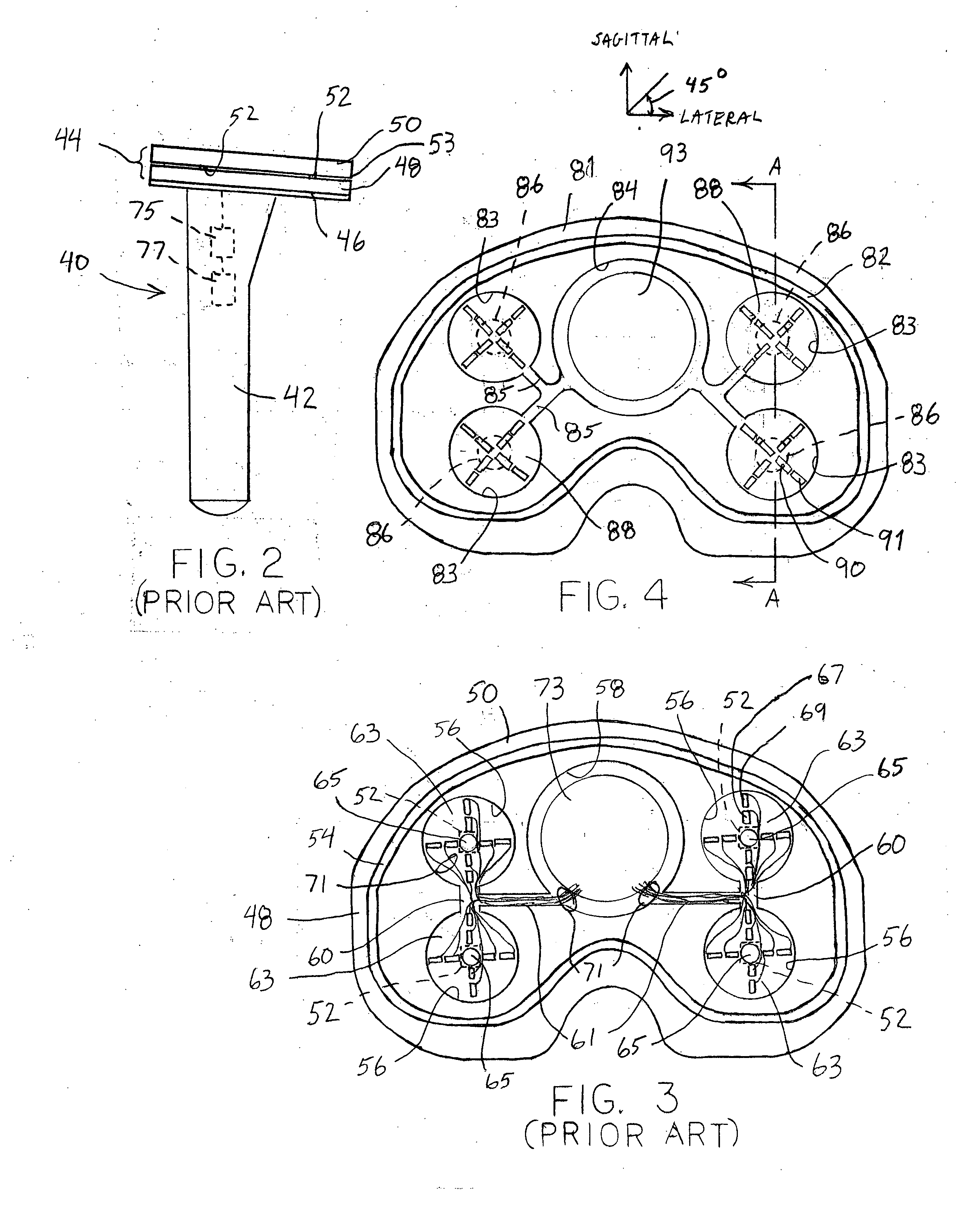
[0035] As shown in FIG. 3, the lower transducer plate 48 of prior telemetric tibial trays utilizes support posts 52 that are square in cross-section. These support posts typically have a dimension of about 2.5 mm on each side. Each support post is integral with the load diaphragm 63 and is aligned with the no-load post 65 projecting into the transducer cavity. The no-load posts produce stress risers at the junc...


PUM


Abstract

A telemetric tibial tray includes a lower plate that defines a plurality of cylindrical transducer cavities having circular load diaphragms. An upper plate is attached to the lower plate through support posts projecting from the load diaphragms. The support posts have a circular cross-section and a diameter of about 5.0 mm. The lower plate further defines wiring channels communicating between the transducer cavities and a central cavity housing the circuit board for the telemetric tray. The wiring channels are arranged at a 45 degree angle relative to the sagittal plane of the knee joint in order to reduce the effects of the wiring channel intersection on the strain sensitivity of the tray. Each transducer cavity includes a radial strain gage array with four pairs of radially aligned strain gages, each pair aligned at a 45 degree angle relative to the sagittal plane of the knee joint. Each pair of strain gages includes an inner gage positioned at the point of maximum positive micro-strain across the diaphragm when loaded, and an outer gage positioned at the point of maximum negative micro-strain, to thereby increase the differential strain measured by the gages and increase the strain sensitivity of the tibial tray.

Description

CROSS-REFERENCE TO RELATED APPLICATIONS [0001] This application claims priority to the following U.S. Provisional Patent Applications: Ser. No. 60 / 486,615, entitled “In Vivo Joint Space Measurement Device and Method”, filed on Jul. 11, 2003, and naming one of the co-inventors of the present application; Ser. No. 60 / 486,762, entitled “In Vivo Joint Implant Cycle Counter”, filed on Jul. 11, 2003, and naming one of the co-inventors of the present application; and Ser. No. 60 / 486,614, entitled “Orthopaedic Element With Self-Contained Data Storage”, filed on Jul. 11, 2003, and naming co-inventors of the present application. The disclosure of each of these provisional applications (60 / 486,615; 60 / 486,762; and 60 / 486,614) is incorporated herein by reference.FIELD OF THE INVENTION [0002] The present invention relates to orthopaedic components configured for implantation within a patient. In particular, the invention concerns systems and methods for evaluating loads within a joint space, and...

Claims


Application Information

Patent Timeline
IPC IPC(8): A61B5/07A61B19/00A61F2/02A61F2/30A61F2/38A61F2/46G01L1/22
CPCA61B5/076A61F2250/0002A61B19/46A61B2019/464A61B2562/02A61F2/38A61F2/3859A61F2/389A61F2002/30133A61F2002/3067A61F2002/30878A61F2002/30892A61F2002/4666A61F2230/0015A61B5/4528A61B2090/064A61B90/06
Inventor DIETZ, TERRYDISILVESTRO, MARKHASTINGS, BOBMATTHEWS, FRANK D.PETRELLA, TONYSLAMIN, JOHN E.TOMASZEWSKI, PAUL
Owner DEPUY PROD INC
Why Eureka
Try Eureka