TFT substrate and scanning antenna provided with TFT substrate
- Summary
- Abstract
- Description
- Claims
- Application Information
AI Technical Summary
Benefits of technology
Problems solved by technology
Method used
Image
Examples
first embodiment
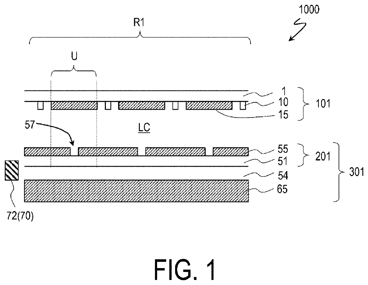
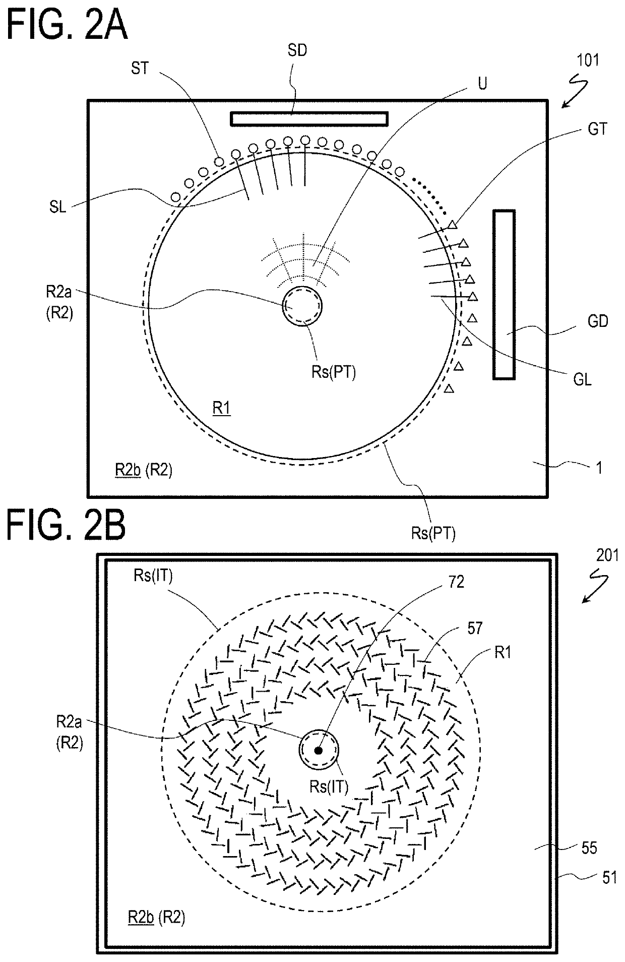
[0116]First, a description is given with reference to FIG. 1 and FIGS. 2A and 2B. FIG. 1 is a schematic partial cross-sectional view of the scanning antenna 1000 near the center thereof as described above in detail, and FIGS. 2A and 2B are schematic plan views illustrating the TFT substrate 101 and the slot substrate 201 in the scanning antenna 1000, respectively.
[0117]The scanning antenna 1000 includes a plurality of antenna units U arranged two-dimensionally. In the scanning antenna 1000 exemplified here, the plurality of antenna units are arranged concentrically. In the following description, the region of the TFT substrate 101 and the region of the slot substrate 201 corresponding to the antenna unit U will be referred to as “antenna unit region”, and be denoted with the same reference numeral U as the antenna unit. In addition, as illustrated in FIGS. 2A and 2B, in the TFT substrate 101 and the slot substrate 201, a region defined by the plurality of two-dimensionally arranged ...
second embodiment
[0207]The scanning antenna of a second embodiment will be described with reference to drawings. The TFT substrate of the scanning antenna of the present embodiment differs from the TFT substrate 101 illustrated in FIG. 2A in that a transparent conductive layer that serves as an upper connection section for each terminal section is provided between the first insulating layer and the second insulating layer of the TFT substrate.
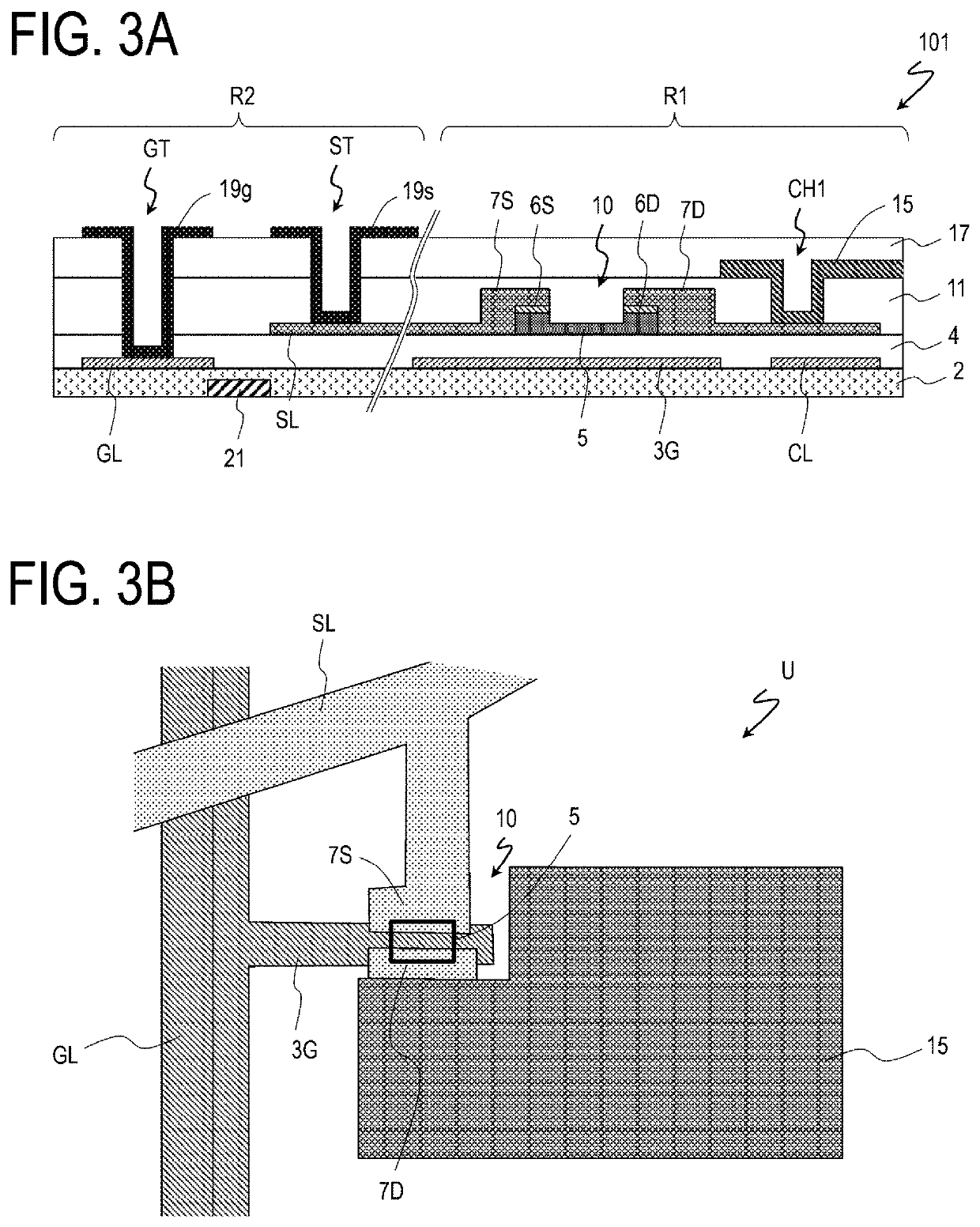
[0208]FIGS. 8A to 8C are cross-sectional views illustrating the gate terminal section GT, the source terminal section ST, and the transfer terminal section PT, respectively, of a TFT substrate 102 in the present embodiment. Constituent elements similar to those in FIGS. 4A to 4C are denoted by the same reference numerals, and the description thereof is omitted. Since the cross-sectional structure of the antenna unit region U is similar to that of the above-described embodiments (FIGS. 3A and 3B), the illustration and description thereof will be omitted.
[0209]Th...
third embodiment
[0223]The scanning antenna of a third embodiment will be described with reference to drawings. The TFT substrate in the scanning antenna of the present embodiment differs from the TFT substrate 102 illustrated in FIGS. 8A to 8C in that the upper connection section made of a transparent conductive film is not provided in the transfer terminal section.
[0224]FIGS. 10A to 10C are cross-sectional views illustrating the gate terminal section GT, the source terminal section ST, and the transfer terminal section PT, respectively, of a TFT substrate 103 in the present embodiment. Constituent elements similar to those in FIGS. 8A to 8C are denoted by the same reference numerals. Since the structure of the antenna unit region U is similar to that of the above-described embodiments (FIGS. 3A and 3B), the illustration and description thereof will be omitted.
[0225]The structures of the gate terminal section GT and the source terminal section ST are similar to the structures of the gate terminal s...
PUM
 Abstract
Description
Claims
Application Information
 - R&D
- Intellectual Property
- Life Sciences
- Materials
- Tech Scout
- Unparalleled Data Quality
- Higher Quality Content
- 60% Fewer Hallucinations
Browse by: Latest US Patents, China's latest patents, Technical Efficacy Thesaurus, Application Domain, Technology Topic, Popular Technical Reports.
© 2025 PatSnap. All rights reserved.Legal|Privacy policy|Modern Slavery Act Transparency Statement|Sitemap|About US| Contact US: help@patsnap.com


