
Stacked power amplifiers using core devices

a power amplifier and core device technology, applied in the field of power amplifiers, can solve the problems of high switching loss, significant power loss, and use of cascode devices

Active Publication Date: 2020-01-09
SHENZHEN GOODIX TECH CO LTD
View PDF2 Cites 3 Cited by
  • Summary
  • Abstract
  • Description
  • Claims
  • Application Information

AI Technical Summary

Benefits of technology

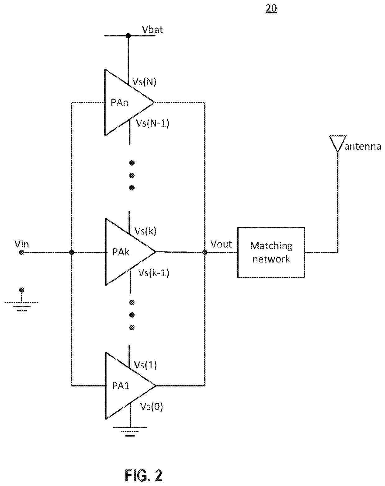
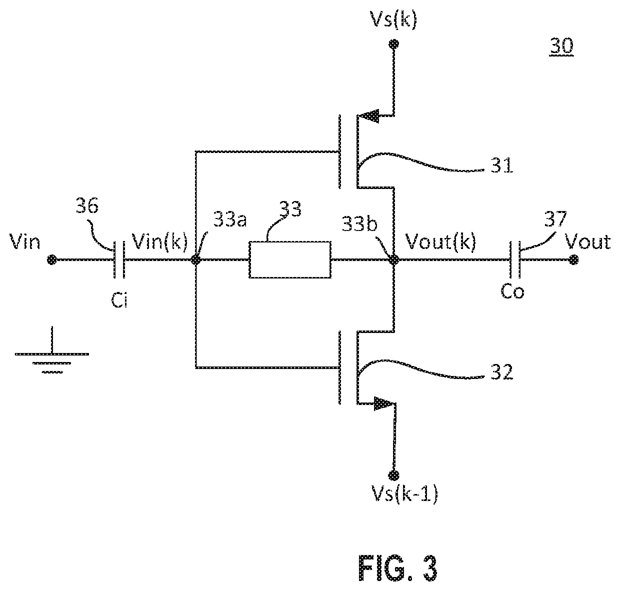
The present patent provides a novel technical solution to overcome the drawbacks of prior art power amplifiers. It describes a power amplifier that includes a plurality of amplifiers stacked in series between a first voltage terminal and a second voltage terminal. Each amplifier has an input and an output capacitor, and a feedback element that is coupled between the input and the output of the amplifier. The amplifiers are designed to amplify low voltage signals using a high-voltage supply. The technical effect of this invention is to provide a more efficient and effective power amplifier for low-voltage signals.

Problems solved by technology

The use of cascode devices adds significant power losses due to their parasitic capacitances and lower transconductances relative to the core devices.
The high voltage transistors have a large parasitic capacitance resulting in high switching losses.

Method used


Image

  • Stacked power amplifiers using core devices
  • Stacked power amplifiers using core devices
  • Stacked power amplifiers using core devices

Examples


Embodiment Construction

[0019]In the following description, numerous specific details are provided for a thorough understanding of the present invention. However, it should be appreciated by those of skill in the art that the present invention may be realized without one or more of these details. In other examples, features and techniques known in the art will not be described for purposes of brevity.

[0020]It should be understood that the drawings are not drawn to scale, and similar reference numbers are used for representing similar elements. It will be understood that, when an element or layer is referred to as “on.”“disposed on,”“adjacent to,”“connected to,” or “coupled to” another element or layer, it can be disposed directly on the other element or layer, adjacent to, connected or coupled to the other element or layer, or intervening elements or layers may also be present. In contrast, when an element is referred to as being “directly on,” directly disposed on,”“directly connected to,” or “directly co...


PUM


Abstract

A power amplifier includes an input terminal configured to receive a low voltage input signal, an output terminal configured to output a high voltage output signal, and a plurality of amplifiers stacked in series between a first voltage terminal and a second voltage terminal. Each of the amplifiers includes an input capacitor, an output capacitor, an input coupled to the input terminal through the input capacitor, an output coupled to the output terminal through the output capacitor, and a feedback element coupled between the input and the output of the amplifier.

Description

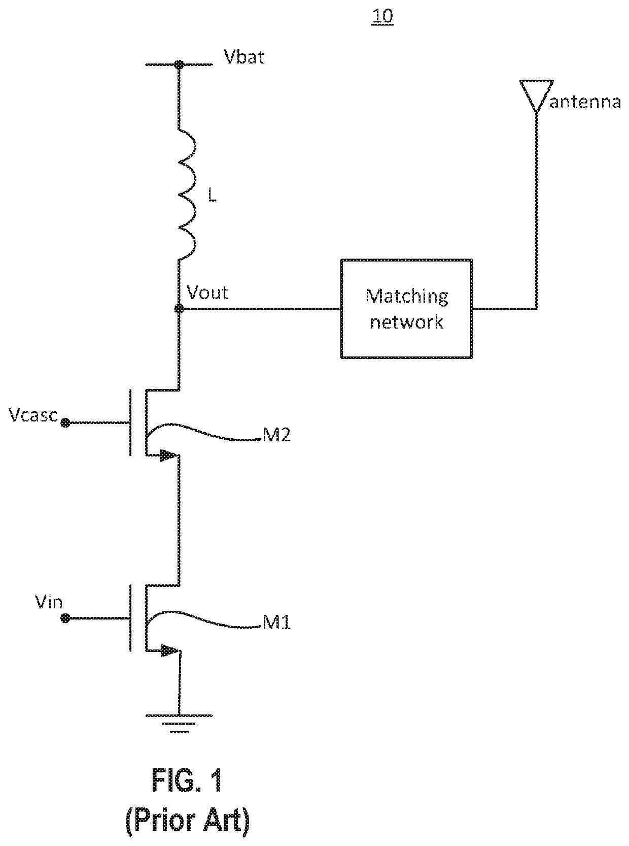
FIELD OF THE INVENTION[0001]The present invention relates to power amplifiers, and more particularly to power amplifiers that employ core devices for high voltage and high frequency applications.BACKGROUND OF THE INVENTION[0002]Portable and wearable wireless devices and systems that operate from batteries require low power operation to extend the battery life. A radio frequency power amplifier (RFPA) is the most power hungry block of a wireless system. A switching RFPA is the most power efficient for constant envelope modulation such as Bluetooth and GSM. The desire to increase output power forces designers to use the battery voltage as the supply voltage for the power amplifier, which, in turn, requires utilizing IO devices as cascodes of the main switching core devices. The use of cascode devices adds significant power losses due to their parasitic capacitances and lower transconductances relative to the core devices.[0003]FIG. 1 is an example cascode power amplifier 10 as known i...

Claims


Application Information

Patent Timeline
Patent Type & Authority Applications(United States)
IPC IPC(8): H03F3/60H03F3/42H03F1/02H03F3/189H03F3/24
CPCH03F1/0283H03F3/423H03F3/24H03F3/604H03F3/189H03F1/223H03F1/523H03F3/195H03F3/2173H03F3/245H03F3/30H03F2200/451H03F2200/516
Inventor EMIRA, AHMEDKHATIB, RAMIHUSSIEN, FAISA
Owner SHENZHEN GOODIX TECH CO LTD
Learn More