Particle Detection Using Thin Lenses

a thin lens and particle technology, applied in particle and sedimentation analysis, measurement devices, instruments, etc., can solve the problems of high inefficiency, incompatibility with the requirement for compact devices, and high cost of expensive and bulky free-space optics, and achieve effective analysis and cytometry, fast and reliable and compact

Active Publication Date: 2020-01-16
INTERUNIVERSITAIR MICRO ELECTRONICS CENT (IMEC VZW)
View PDF0 Cites 7 Cited by
  • Summary
  • Abstract
  • Description
  • Claims
  • Application Information

AI Technical Summary

Benefits of technology

[0005]It is an object of embodiments of the present invention to provide a fast, reliable and compact optica

Problems solved by technology

This requires expensive and bulky free-space optics.
This is not compatible with the requirement for compact devices, which are desirable for point-of-car

Method used


Image

  • Particle Detection Using Thin Lenses
  • Particle Detection Using Thin Lenses
  • Particle Detection Using Thin Lenses

Examples


Embodiment Construction

[0046]The present invention will be described with respect to particular embodiments and with reference to certain drawings but the invention is not limited thereto but only by the claims. The drawings described are only schematic and are non-limiting. In the drawings, the size of some of the elements may be exaggerated and not drawn on scale for illustrative purposes. The dimensions and the relative dimensions do not correspond to actual reductions to practice of the invention. In the different drawings, the same reference signs refer to the same or analogous elements.

[0047]The terms first, second and the like in the description and in the claims, are used for distinguishing between similar elements and not necessarily for describing a sequence, either temporally, spatially, in ranking or in any other manner. It is to be understood that the terms so used are interchangeable under appropriate circumstances and that the embodiments of the invention described herein are capable of ope...


PUM


Abstract

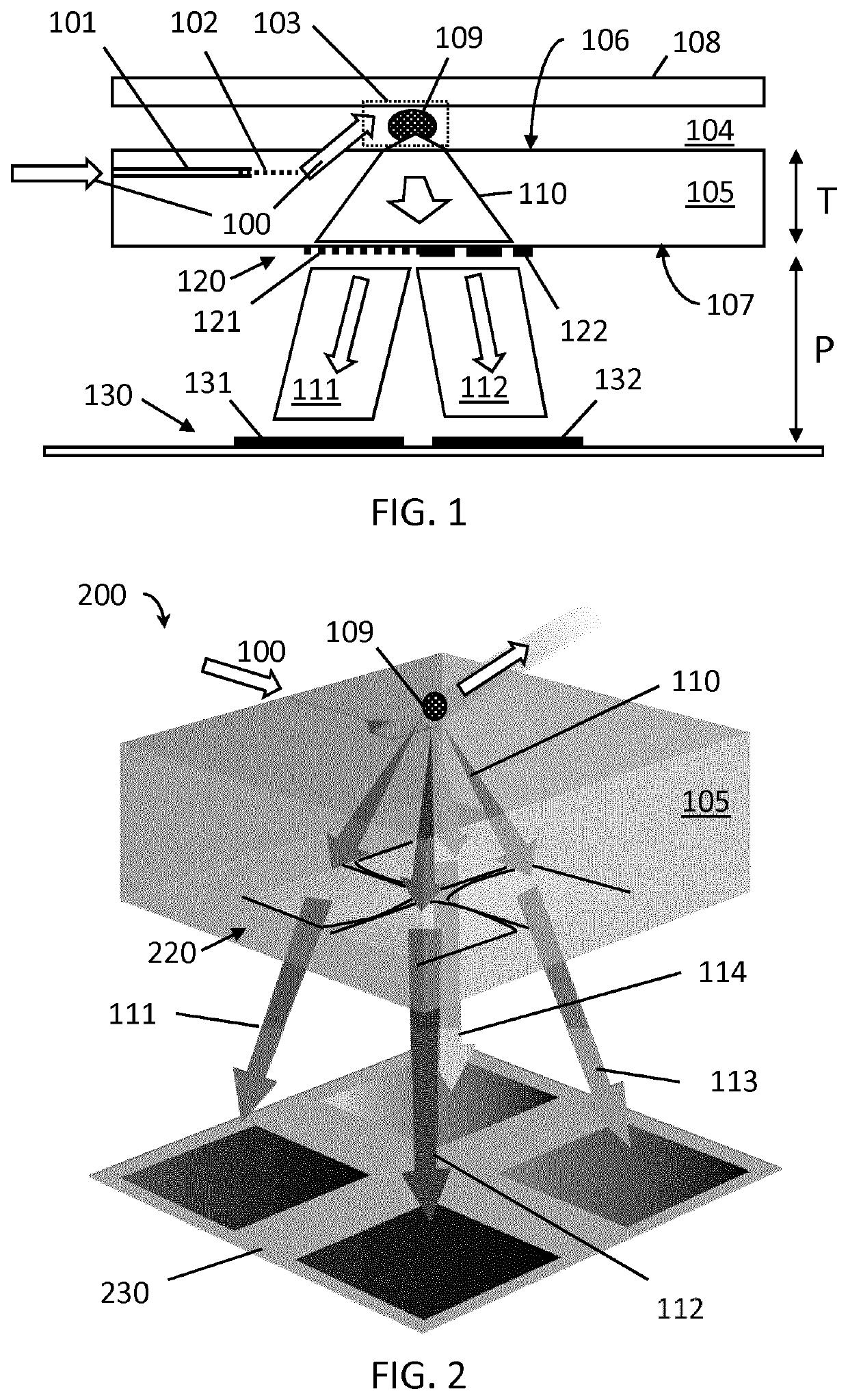
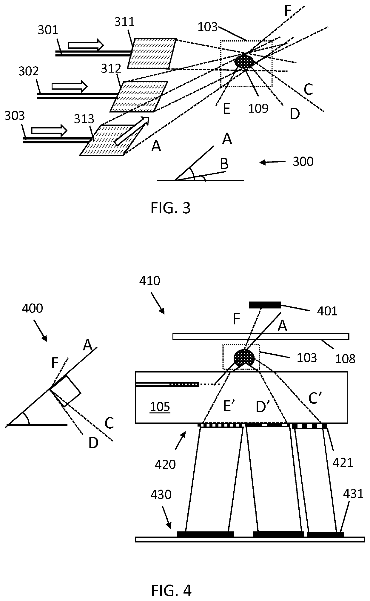
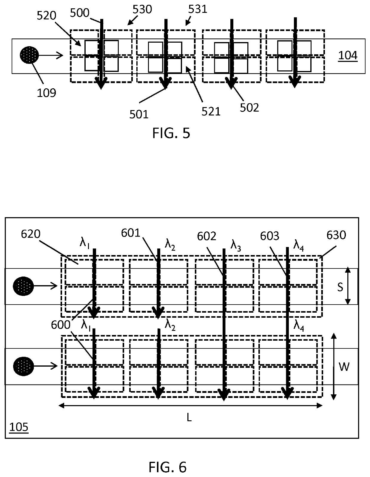
An optical excitation system comprises a substrate (105) comprising at least one delivery means (104), for delivering analytes (109) into at least one region of interest (103), at least one radiation carrier (101) for directing at least one radiation beam from the at least one radiation carrier (101) into the at least one region of interest (103). The substrate (105) includes a thin lens system (120) comprising at least a first thin lens (121), for collimating radiation from the at least one region of interest (103) to a remote detection system (130). A particle sensor and sensing system comprising the excitation system are also provided, for example a modular particle sensor and modular sensing system, wherein the optical excitation system may be single use and disposable.

Description

FIELD OF THE INVENTION[0001]The present invention relates to the field of particle detection and analysis. More specifically it relates to devices for particle detection and analysis via optical means, and to manufacturing methods thereof. In particular embodiments, it relates to luminescence (e.g. fluorescence)-based detection, Raman scattering-based detection, suitable for flow analysis. Other detection principles which may be used in the present invention may for instance be absorption or light scattering.BACKGROUND OF THE INVENTION[0002]Cytometry comprises the analysis and sorting of single analytes in a flow, typically a continuous flow, of particles. The analytes may include a variety of types, typically cells, but also it can be extended to other particles such as viruses, antibodies, etc. A cytometer typically comprises means of delivering analytes to a detection region, or region of interest (ROI), for example in a flowing stream (e.g. in a fluid, etc.). It also comprises e...

Claims


Application Information

Patent Timeline
IPC IPC(8): G01N15/14G01N21/47
CPCG01N2015/1006G01N15/1434G01N21/47G01N15/1436G01N15/147
Inventor VERCRUYSSE, DRIES
Owner INTERUNIVERSITAIR MICRO ELECTRONICS CENT (IMEC VZW)
Why Eureka
Try Eureka