Clock generating circuit and hybrid circuit

a clock generation circuit and hybrid circuit technology, applied in the direction of pulse generators, pulse generators, electric pulse generator circuits, etc., can solve the problems of acdr circuit and cmu design dilemmas, jitter of the output clock of the cmu, and difficulty in meeting the requirements of both sides of the low pass filter design

Active Publication Date: 2020-01-16
REALTEK SEMICON CORP
View PDF0 Cites 4 Cited by
  • Summary
  • Abstract
  • Description
  • Claims
  • Application Information

AI Technical Summary

Benefits of technology

[0007]The present invention also discloses a hybrid circuit capable of operating in one of an analog clock data recovery (ACDR) mode and a clock multiplication unit (CMU) mode. According to an embodiment of the present invention, the hybrid circuit includes a CMU circuit, a sampling circuit, a phase detector, and a multiplexer. The CMU circuit includes a phase frequency detector, a charge pump, a filter, a ring oscillator, and a loop divider, in which the charge pump is configured to generate a voltage control signal according to an output of one of the phase detector and the phase frequency detector, the filter is configured to determine at least one of a first voltage signal and a second voltage signal, that is outputted to the ring oscillator, according to the voltage control signal of the charge pump, and the ring oscillator is configured to output at least one clock according to the first voltage sig

Problems solved by technology

However, the requirements for a low pass filter of the ACDR circuit and a low pass filter of the CMU are different so that it is very difficult to design a low pass filter meeting the requirements of the both sides. FIG. 1 shows a second-order low pass filter 100 which can be applied to

Method used


Image

  • Clock generating circuit and hybrid circuit
  • Clock generating circuit and hybrid circuit
  • Clock generating circuit and hybrid circuit

Examples


Embodiment Construction

[0018]The present invention includes a clock generating circuit and a hybrid circuit capable of operating for an analog clock data recovery (ACDR) mode and a clock multiplication unit (CMU) mode adaptively so that the present invention can reduce the loop latency of an ACDR circuit in the ACDR mode and deeply suppress reference jitter with proper loop stability and bandwidth of an CMU circuit in the CMU mode.

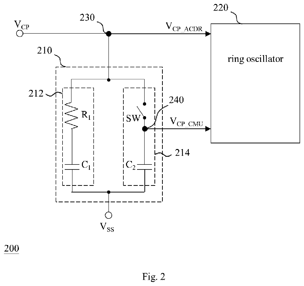
[0019]FIG. 2 shows an embodiment of the clock generating circuit of the present invention. The clock generating circuit 200 of FIG. 2 includes a filter 210 and a ring oscillator 220. The filter 210 is configured to receive an input signal VCP and thereby determine a first voltage signal VCP_ACDR and a second voltage signal VCP_CMU according to the input signal VCP, in which the first voltage signal VCP_ACDR and the second voltage signal VCP_CMU are outputted to the ring oscillator 220 via a first node 230 and a second node 240 respectively. The filter 210 includes a first filter...


PUM


Abstract

Disclosed is a clock generating circuit including a filter and a ring oscillator. The filter receives an input signal and accordingly determines a first voltage signal and a second voltage signal that are outputted via a first node and a second node respectively. The filter includes a first filtering circuit and a second filtering circuit coupled in parallel between the first node and a reference voltage terminal; the second filtering circuit includes a switch and a capacitor connected in series, in which the second node is between the switch and the capacitor, and the switch is turned off in an analog clock data recovery (ACDR) mode and turned on in a clock multiplication unit (CMU) mode. The ring oscillator outputs at least one clock according to the first voltage signal in the ACDR mode and outputs at least one clock according to the second voltage signal in the CMU mode.

Description

BACKGROUND OF THE INVENTION1. Field of the Invention[0001]The present invention relates to a clock generating circuit and a hybrid circuit, especially to a clock generating circuit and a hybrid circuit capable of operating for an analog clock data recovery (ACDR) mode and a clock multiplication unit (CMU) mode adaptively.2. Description of Related Art[0002]A conventional Serializer / Deserializer (SerDes) physical layer circuit (PHY) includes a receiving circuit and a transmitting circuit. The receiving circuit includes an analog clock data recovery (ACDR) circuit and the transmitting circuit includes a clock multiplication unit (CMU). Each of the ACDR circuit and the CMU includes a charge pump, a low pass filter, and a voltage-controlled oscillator; accordingly, if the ACDR circuit and the CMU can share the same charge pump, low pass filter and voltage-controlled oscillator, the total circuit area of the ACDR circuit and the CMU can be reduced.[0003]However, the requirements for a low...

Claims


Application Information

Patent Timeline
IPC IPC(8): H04L7/033H03L7/08H03L7/089H03L7/099H04L7/00
CPCH03L7/0807H03L7/0891H04L7/0037H03L7/0995H04L7/0331H04L7/0087H03K3/011H03K3/021H03L7/093H03L7/087H03L7/22
Inventor LIU, JIANHE, WEIXIONGLOU, JIANING
Owner REALTEK SEMICON CORP
Why Eureka
Try Eureka