
System and method of predictive fault mitigation for electric power steering system in a vehicle

a technology of electric power steering and system, which is applied in the direction of vehicle position/course/altitude control, process and machine control, instruments, etc., can solve the problems of reducing or limiting the capabilities electric power steering system to experience low input voltage, and reducing the functionality of electric power steering system

Inactive Publication Date: 2020-01-23
GM GLOBAL TECH OPERATIONS LLC
View PDF0 Cites 2 Cited by
  • Summary
  • Abstract
  • Description
  • Claims
  • Application Information

AI Technical Summary

Benefits of technology

The patent text discusses factors that can make the electric power steering system weaker, such as low battery voltage or increased friction. In a semi-autonomous or fully autonomous vehicle, the system should still work within its capabilities. The technical effect is to ensure the electric power steering system works effectively and efficiently in all driving situations.

Problems solved by technology

Certain factors may reduce the functionality of the electric power steering system.
For example, a low battery voltage, an increase in steering friction and / or steering resistance, or an increase in electrical resistance in an electrical circuit of the electric power steering system, may reduce or limit the capabilities of the electric power steering system.
A low voltage VB from the energy source, an increase in the resistance RC in the circuit between the energy source and the electric power steering system, and / or an increase in the friction coefficient of the electric power steering system Cfr, may cause the electric power steering system to experience low input voltages, which may potentially interrupt autonomous steering operations of the vehicle.
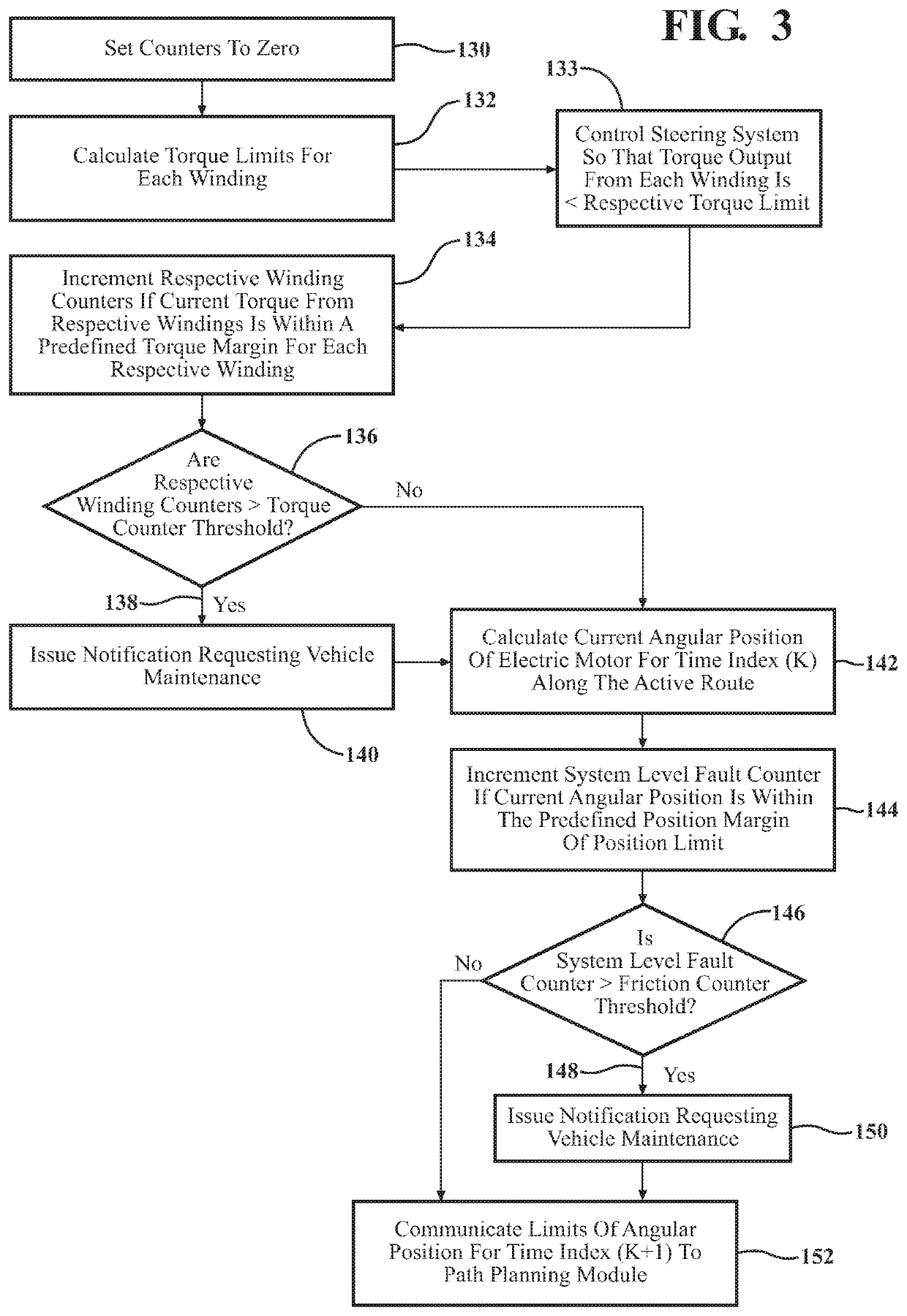
Additionally, the computing device may also set a system level fault counter to zero.

Method used


Image

  • System and method of predictive fault mitigation for electric power steering system in a vehicle
  • System and method of predictive fault mitigation for electric power steering system in a vehicle
  • System and method of predictive fault mitigation for electric power steering system in a vehicle

Examples


Embodiment Construction

[0022]Those having ordinary skill in the art will recognize that terms such as “above,”“below,”“upward,”“downward,”“top,”“bottom,” etc., are used descriptively for the figures, and do not represent limitations on the scope of the disclosure, as defined by the appended claims. Furthermore, the teachings may be described herein in terms of functional and / or logical block components and / or various processing steps. It should be realized that such block components may be comprised of a number of hardware, software, and / or firmware components configured to perform the specified functions.

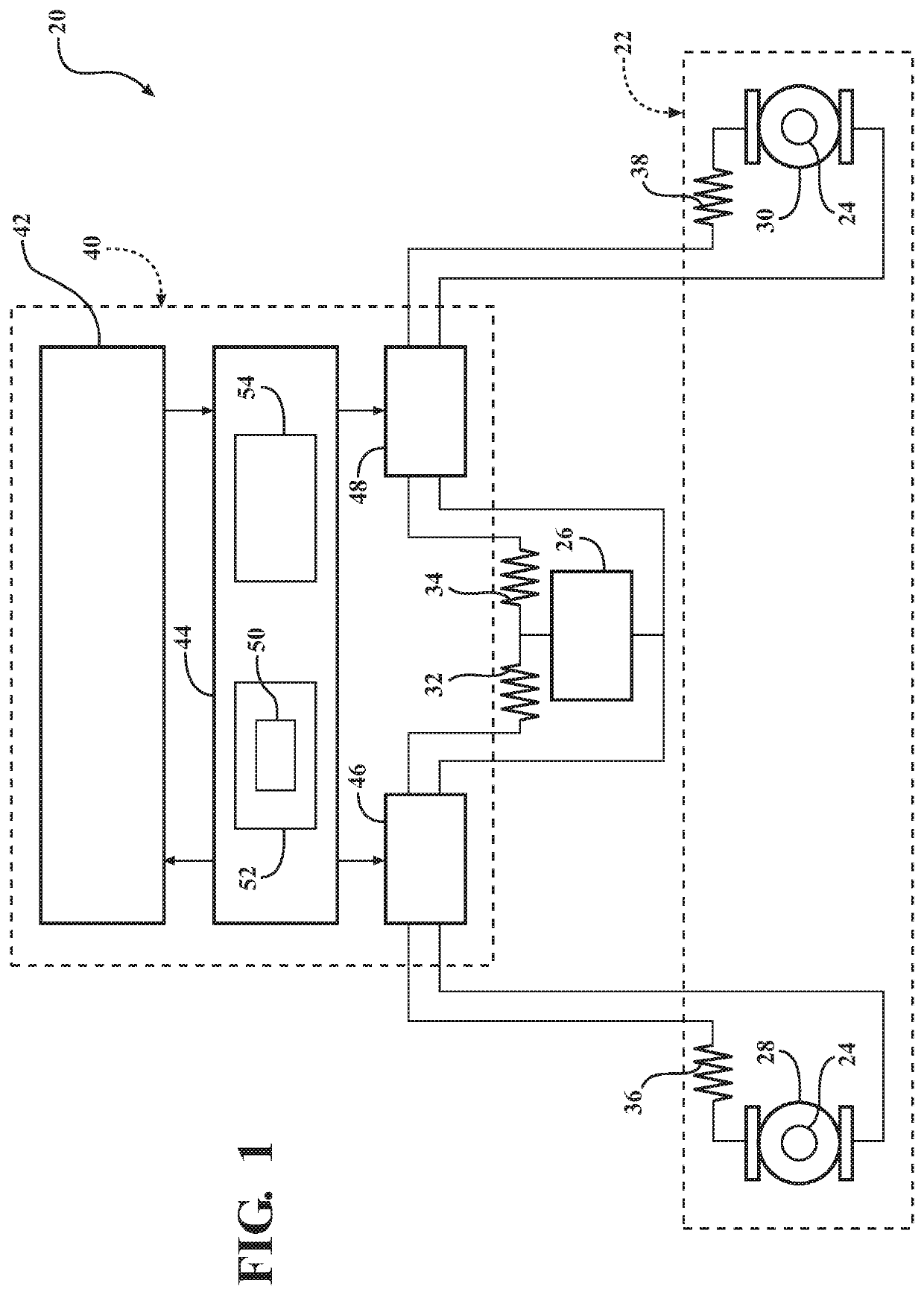
[0023]Referring to the FIGS., wherein like numerals indicate like parts throughout the several views, an electric power steering system is generally shown at 20 in FIG. 1. The electric power steering system 20 may be configured in a suitable manner understood by those skilled in the art. Referring to FIG. 1, the electric power steering system 20 may include, for example, an electric motor 22 that is oper...


PUM


Abstract

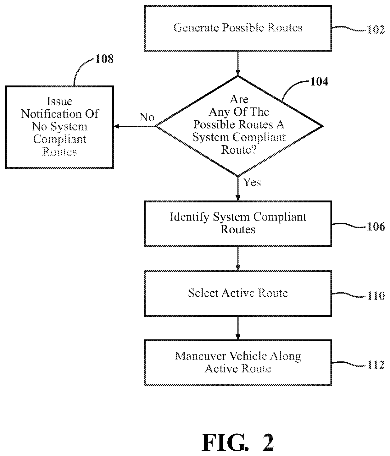
A method of controlling a vehicle having an electric power steering system includes generating a plurality of possible routes. Each of the plurality of possible routes that require a steering torque that is within an available torque range is identified as a system compliant route. Each of the plurality of possible routes that require an angular position of an electric motor of the electric power steering system at all time indices throughout that route that are within an available motor position range are also identified as a system compliant route. One of the identified system compliant routes is selected based on at least one selection criteria, and designated as an active route. The electric power steering system is then controlled to maneuver the vehicle along the active route. The electric power steering system is monitored as the vehicle moves along the active route to identify degradation of its capabilities.

Description

INTRODUCTION[0001]The disclosure generally relates to a method of controlling a vehicle having an electric power steering system.[0002]Some vehicles are equipped with an electric power steering system that may be controlled by a computing device to provide semi-autonomous and / or fully autonomous vehicle steering. Electric power steering systems use an electric motor to provide a torque to a shaft to assist an operator in turning the steering wheels of the vehicle. The electric power steering system may be controlled by a computing device to automatically apply torque to the steering system to enable semi-autonomous and / or fully autonomous vehicle operations.[0003]Certain factors may reduce the functionality of the electric power steering system. For example, a low battery voltage, an increase in steering friction and / or steering resistance, or an increase in electrical resistance in an electrical circuit of the electric power steering system, may reduce or limit the capabilities of ...

Claims


Application Information

Patent Timeline
IPC IPC(8): B62D5/04G05D1/00G05D1/02G07C5/00G07C5/08
CPCB62D5/0484B62D5/0487G05D1/0061G07C5/0816G05D1/0088G07C5/006G05D1/021B62D5/0463B62D5/0481B62D6/00B62D15/0285
Inventor LIN, WEN-CHIAODU, XINYUSISKOY, BRIAN N.
Owner GM GLOBAL TECH OPERATIONS LLC
Learn More