
Vapor chamber, electronic device, metallic sheet for vapor chamber and manufacturing method of vapor chamber

a technology of metallic sheet and manufacturing method, which is applied in the direction of lighting and heating apparatus, modifications of conduction heat transfer, and semiconductor/solid-state device details, etc. it can solve the problems of metallic sheet being recessed inwardly along the groove, reducing the heat transport efficiency of the evaporating portion, and affecting the flow of working fluid in liquid form. , to achieve the effect of improving the thermal transport efficiency and improving the transport function of working fluid in liquid form

Active Publication Date: 2020-01-23
DAI NIPPON PRINTING CO LTD
View PDF0 Cites 6 Cited by
  • Summary
  • Abstract
  • Description
  • Claims
  • Application Information

AI Technical Summary

Benefits of technology

The present invention is about a vapor chamber used in electronic devices. The vapor chamber is made of two metallic sheets with grooves on one sheet. When the vapor chamber is recessed, the metallic sheet can deform and the grooves can become narrow, which can increase the resistance to the fluid and reduce the supply of fluid to the evaporating portion, resulting in lower thermal transport efficiency. The invention seeks to improve the cross-sectional area of the flow path of the liquid flow path portion to improve the transport function of the working fluid and enhance the thermal transport efficiency of the vapor chamber. This will be achieved by securing the cross-sectional area of the flow path of the liquid flow path portion and avoiding the deformation of the metallic sheet.

Problems solved by technology

However, when a plurality of grooves are formed in a lattice shape, a problem can occur due to a pressure received from the outside air.
Consequently, the metallic sheet has a risk of being recessed inwardly along the grooves.
In such a case, such a problem occurs that the amount of heat transport from the evaporating portion is reduced, and thermal transport efficiency is lowered.

Method used


Image

  • Vapor chamber, electronic device, metallic sheet for vapor chamber and manufacturing method of vapor chamber
  • Vapor chamber, electronic device, metallic sheet for vapor chamber and manufacturing method of vapor chamber
  • Vapor chamber, electronic device, metallic sheet for vapor chamber and manufacturing method of vapor chamber

Examples


first embodiment

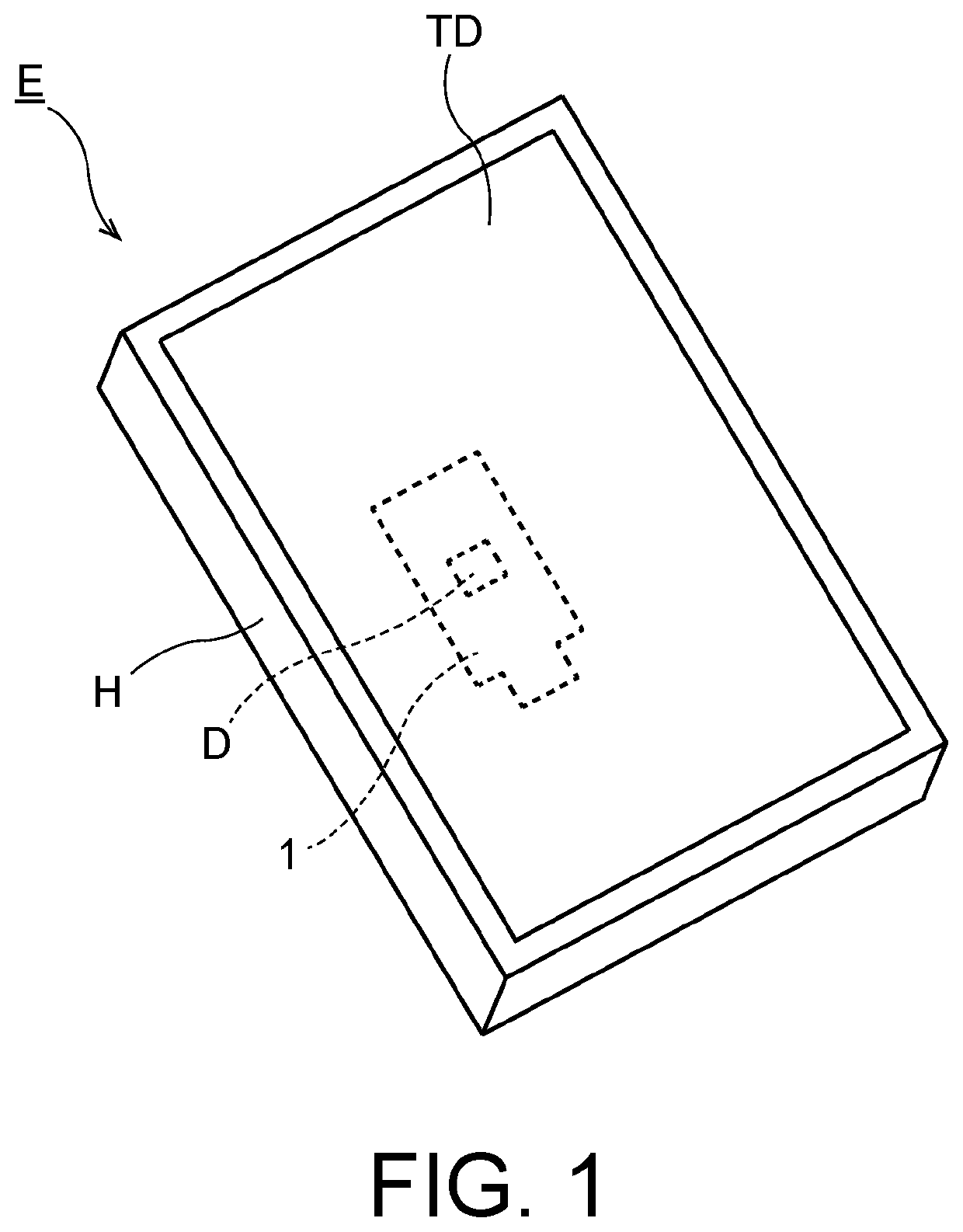
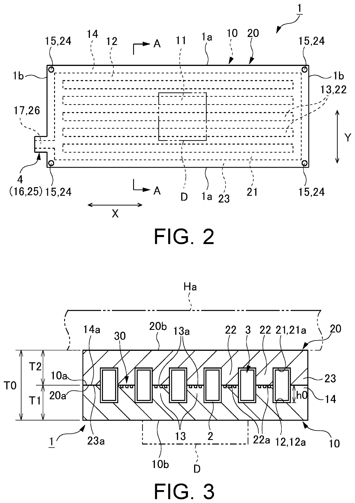
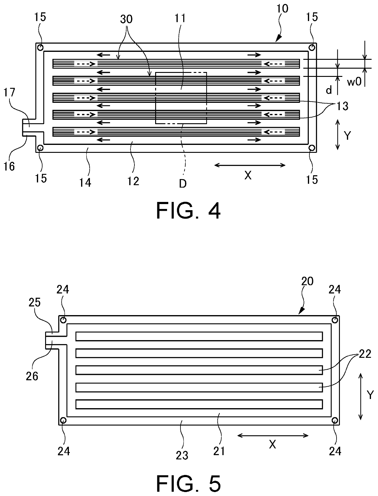
[0104]A vapor chamber, an electronic device, a metallic sheet for the vapor chamber and a manufacturing method of the vapor chamber according to a first embodiment of the present invention will be explained using FIGS. 1 to 18. A vapor chamber 1 according to this embodiment is an apparatus mounted on an electronic device E for cooling a device D as a heating element housed in the electronic device E. As an example of the device D, an electronic device accompanied with heat generation (a device to be cooled) such as a central processing unit (CPU), a light-emitting diode (LED) and a power transistor, which is used in a mobile terminal and the like such as a portable terminal or a tablet terminal, can be listed.

[0105]Here, firstly, an explanation will be made on the electronic device E on which the vapor chamber 1 is mounted according to this embodiment taking a tablet terminal as an example. As shown in FIG. 1, the electronic device E (tablet terminal) includes a housing H, the devic...

second embodiment

[0201]Next, a vapor chamber, an electronic device, a metallic sheet for the vapor chamber and a manufacturing method of the vapor chamber according to a second embodiment of the present invention will be explained using FIGS. 19 to 22.

[0202]In the second embodiment as shown in FIGS. 19 to 22, a main difference is that a width of the first to fourth communicating grooves is larger than a width of the first to fourth main flow grooves, and the other configurations are substantially similar to those in the first embodiment shown in FIGS. 1 to 18. Additionally, in FIGS. 19 to 22, the same components as in the first embodiment shown in FIGS. 1 to 18 are applied the same reference numerals, and a detailed explanation thereof is omitted.

[0203]As shown in FIG. 19, in this embodiment, a width w3′ of the first communicating groove 51 to the fourth communicating groove 54 is larger than the width w1 of the first main flow groove 31 to the fourth main flow groove 34 (more specifically, the widt...

third embodiment

[0234]Next, a vapor chamber, a metallic sheet for the vapor chamber and a manufacturing method of the vapor chamber according to a third embodiment of the present invention will be explained using FIGS. 23 to 25.

[0235]In the third embodiment shown in FIGS. 23 to 25, a main difference is that a main flow groove convex portion protrudes in the first to fourth main flow grooves, and a communicating groove convex portion protrudes in the first to fourth communicating grooves, and the other configurations are substantially the same as in the second embodiment as shown in FIGS. 19 to 22. Additionally, in FIGS. 23 to 25, the same components as those in the second embodiment as shown in FIGS. 19 to 22 are applied the same reference numerals, and a detailed explanation thereof is omitted.

[0236]As shown in FIG. 23, in this embodiment, the upper metallic sheet 20 includes a plurality of main flow groove convex portions 27 provided in the lower surface 20a. Each of the main flow groove convex p...


PUM


Abstract

A liquid flow path portion of a vapor chamber according to this invention includes a first main flow groove, a second main flow groove and a third main flow groove. A first convex array including a plurality of first convex portions arranged via a first communicating groove is provided between the first main flow groove and the second main flow groove. A second convex array including a plurality of second convex portions arranged via a second communicating groove is provided between the second main flow groove and the third main flow groove. The main flow groove includes a first intersection at which at least a part of the first communicating groove faces each second convex portion and a second intersection at which at least a part of the second communicating groove faces each first convex portion.

Description

TECHNICAL FIELD[0001]The present invention relates to a vapor chamber including a sealed space in which a working fluid is enclosed, an electronic device, a metallic sheet for the vapor chamber and a manufacturing method of the vapor chamber.BACKGROUND ART[0002]A device accompanied with heat generation such as a central processing unit (CPU), a light-emitting diode (LED) and a power semiconductor, which is used in a mobile terminal and the like including a portable terminal or a tablet terminal, is cooled by a heat release member such as a heat pipe (for example, see Patent Literatures 1 to 5.) In recent years, to make a mobile terminal etc. thinner, thickness reduction of the heat release member has been requested, and development has been advanced for a vapor chamber which can be thinner than the heat pipe. In the vapor chamber, a working fluid is enclosed, and the working fluid absorbs heat in the device and releases the heat to the outside, whereby the device is cooled.[0003]Mor...

Claims


Application Information

Patent Timeline
Patent Type & Authority Applications(United States)
IPC IPC(8): F28D15/02H01L23/427F28D15/04H05K7/20
CPCH01L23/427F28D15/0266F28D15/046H05K7/20309F28D15/0233F28D15/0283H05K7/2039F28D2021/0029F28F3/12F28D2021/0028H05K7/20336
Inventor TAKAHASHI, SHINICHIROHIRATA, KENROOTA, TAKAYUKIHASHIMOTO, TAIZOTAKEMATSU, KIYOTAKA
Owner DAI NIPPON PRINTING CO LTD
Learn More