Motor controller and motor control method

a technology of motor controller and control method, which is applied in the direction of control system, dynamo-electric machine testing, instruments, etc., can solve the problems of reducing the output of the motor or overheating the motor, requiring a great deal requiring a large amount of time and effort, so as to simplify and efficiently inspect the winding specifications of the motor

Inactive Publication Date: 2020-01-30
FANUC LTD
View PDF0 Cites 1 Cited by
  • Summary
  • Abstract
  • Description
  • Claims
  • Application Information

AI Technical Summary

Benefits of technology

[0019]According to the present invention, compared to the conventional inspection conducted by actually measuring a voltage value, etc., failure or no-failure can be judged by determining the characteristics of a motor on the basis of a voltage command value output during control of a current in the motor. This makes it possible to inspect winding specifications of the motor more simply and efficiently.

Problems solved by technology

Connection error in such motor power lines (winding specification error in the motor) is directly associated with trouble such as reduction in motor output or overheating of the motor.
This inevitably necessitates use of a dedicated inspection device or measurement device.
Additionally, applying these inspection / control methods to inspection for checking connection abnormality in the attached motor, for example, causes seriously poor usability and requires a great deal of time and effort.

Method used


Image

  • Motor controller and motor control method
  • Motor controller and motor control method
  • Motor controller and motor control method

Examples


Embodiment Construction

[0024]A motor controller and a motor control method according to an embodiment of the present invention will be described below by referring to FIGS. 1 to 4.

[0025]The embodiment relates to a motor controller and a motor control method allowing inspection for determining, for example, whether winding specification error (connection error) has occurred in an attached motor more simply and efficiently.

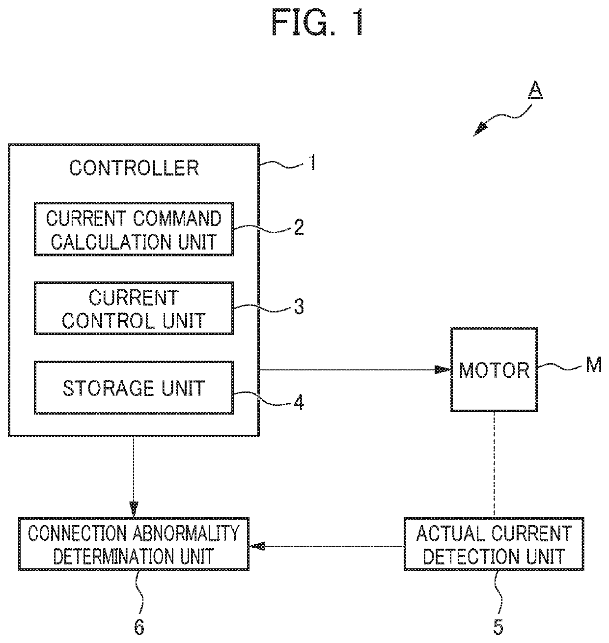
[0026]As shown in FIG. 1, a motor controller A (controller 1 of a motor inspection device A) of the embodiment includes a current command calculation unit 2 that calculates a current command for a current to flow in a motor, a current control unit 3 that controls a motor current by changing a voltage command value for a voltage to be applied to a motor M during driving control of the motor M, and a storage unit 4 that stores a parameter for driving the motor M.

[0027]The motor controller A of the embodiment further includes an actual current detection unit 5 that measures / detects an actual...


PUM


Abstract

To provide a motor controller and a motor control method allowing inspection for checking the presence or absence of specification error in motor winding to be conducted more simply, efficiently, and with high accuracy. A voltage command value as a command value for driving control of a motor and an excitation frequency are sampled. An actual current flowing in the motor being driven under control is detected. Theoretical values of a voltage command value, a current, and an excitation frequency are determined from a parameter for driving the motor and a condition at the time of driving. The theoretical values of the voltage command value, the current, and the excitation frequency are compared with the values of the voltage command value, the current, and the excitation frequency respectively at the time of the driving, and it is determined that there is winding abnormality if differences between the comparable values exceed a threshold range set in advance.

Description

[0001]This application is based on and claims the benefit of priority from Japanese Patent Application No. 2018-138651, filed on 24 Jul. 2018, the content of which is incorporated herein by reference.BACKGROUND OF THE INVENTIONField of the Invention[0002]The present invention relates to a motor controller and a motor control method.Related Art[0003]Conventionally, motors have heavily been used in various types of equipment and devices. For example, driving motors for use in electric vehicles and hybrid vehicles, and motors for operations such as zooming and focusing inside lens barrels of video cameras and digital still cameras are significantly important for ensuring performance and required to output intended power with high accuracy relative to a control amount.[0004]There has been a device (method) for inspecting such motors during attachment or manufacture of the motors. This device (method) includes an inverter, a motor control ECU, a torque meter, a load motor 5, a load motor...

Claims


Application Information

Patent Timeline
Patent Type & Authority Applications(United States)
IPC IPC(8): H02P29/40G01R31/06G01R31/34
CPCG01R31/343G01R31/346G01R31/34G01R31/72H02P29/40
Inventor MORITA, YUUKITSUTSUMI, TOMOHISA
Owner FANUC LTD
Why Eureka
Try Eureka