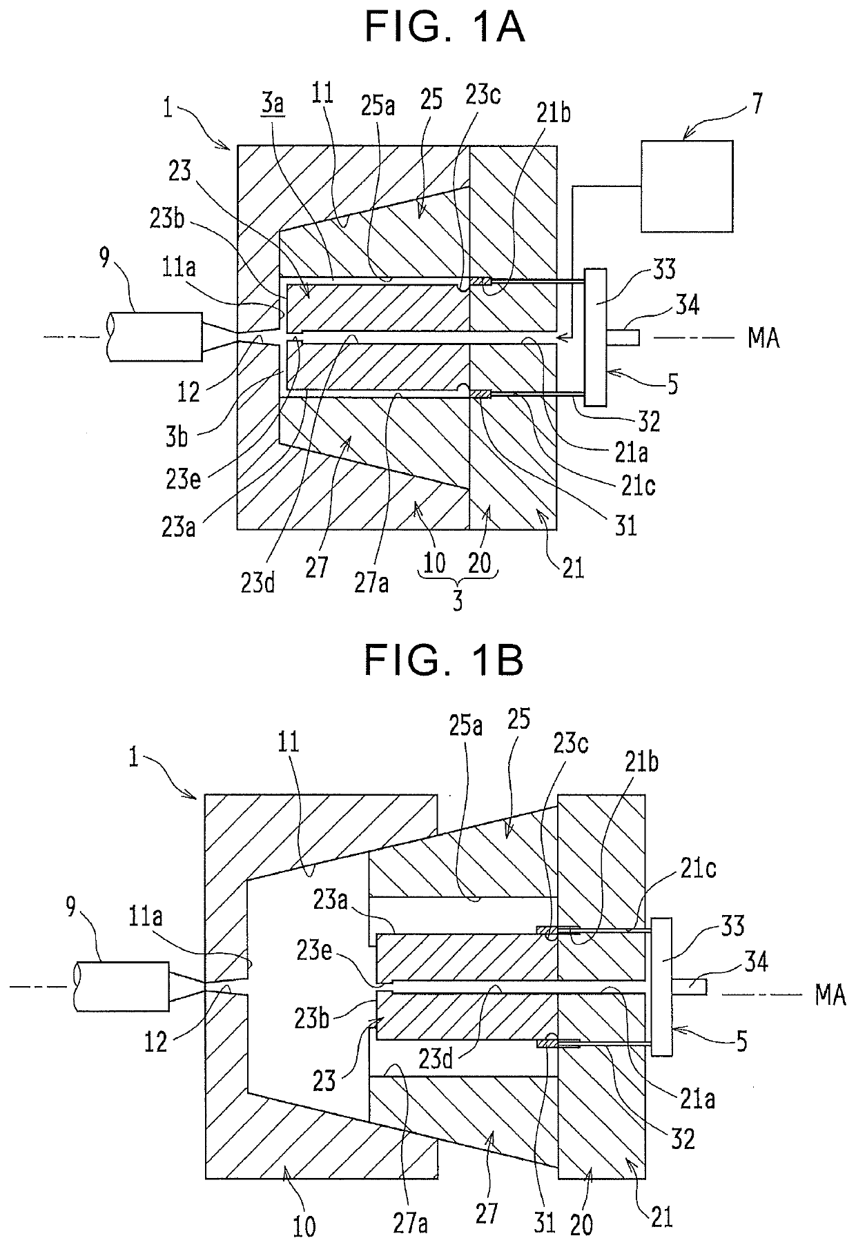
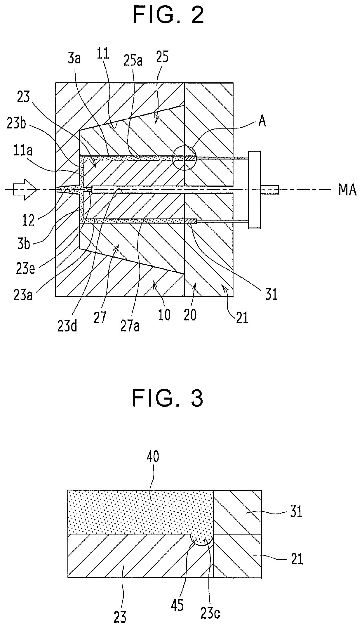
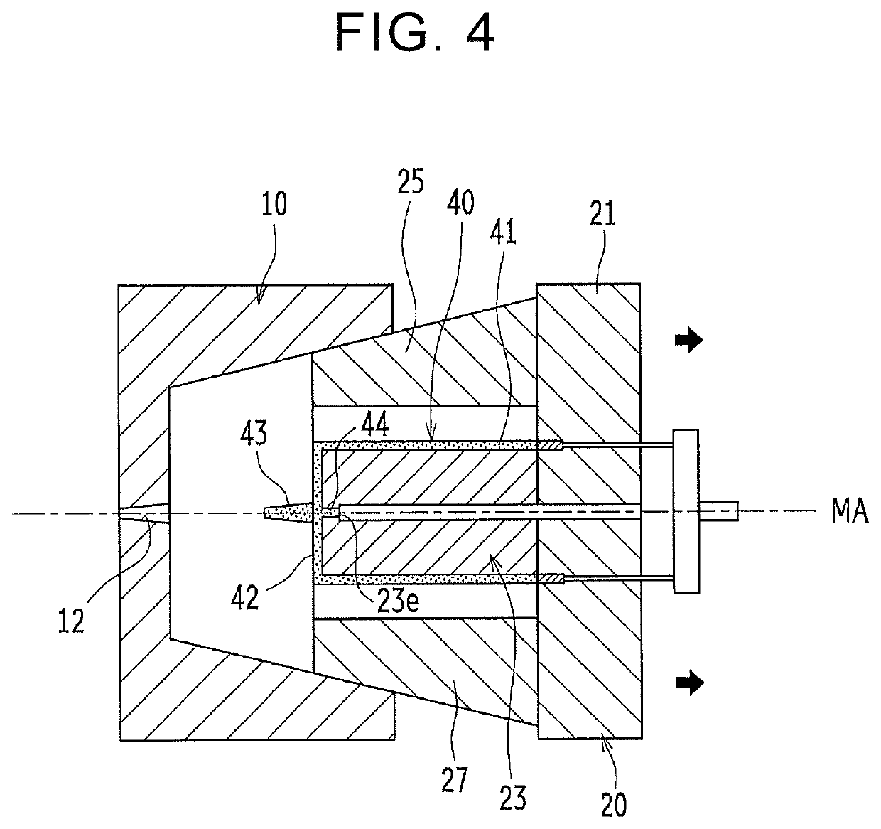
Injection molding die, injection molding system, and injection molding method

Inactive Publication Date: 2020-02-06
TOYOTA JIDOSHA KK
View PDF0 Cites 2 Cited by
  • Summary
  • Abstract
  • Description
  • Claims
  • Application Information

AI Technical Summary

Benefits of technology

The patent describes a technology that allows for the accurate and efficient production of resin hollow bodies with straight tubular portions that do not have a die-removing taper. The method and system use an injection molding die that reduces damage to the resin during demolding. Overall, this technology simplifies the process of molding complex resin shapes while improving their quality.

Problems solved by technology

Accordingly, it is difficult to pull off the resin hollow body from the straight core, and if the resin hollow body is forcibly removed from the straight core, an inner peripheral surface of the resin hollow body might be damaged.
Accordingly, in a case where a container or the like is manufactured by use of such a resin hollow body, there is such a problem that the volume of the container decreases and an amount of contents to be stored therein decreases as compared to a case of using a resin hollow body that does not have a die-removal taper.
However, the technique in which a resin hollow body is formed by moving a floating core has such a problem that the accuracy of the plate thickness of the resin hollow body is low because it is difficult to control the behavior of the floating core.
Further, the technique in which a resin hollow body is pulled off by deforming a core after molding has such a problem that a manufacturing cost increases because a special core is required and the configuration of a molding die is complicated.

Method used


Image

  • Injection molding die, injection molding system, and injection molding method
  • Injection molding die, injection molding system, and injection molding method
  • Injection molding die, injection molding system, and injection molding method

Examples


modification 1

[0103]The present modification is different from the above embodiment in that a generally hemispherical dome portion 66 is formed in a front end portion of the resin hollow body 60 in the die-removal direction, as illustrated in FIG. 10. The following mainly describes points different from the above embodiment.

[0104]A resin hollow body 60 includes a cylindrical portion (a straight tubular portion) 61, the generally hemispherical dome portion 66 formed in an end portion of the cylindrical portion 61 on the second side in the axial direction, a cylindrical mouthpiece attachment portion 67 formed so as to penetrate through the dome portion 66 in the axial direction, and a closing portion 62 configured to close an end portion of the mouthpiece attachment portion 67 on the first side in the axial direction. A protrusion portion (not shown) similar to the protrusion portion 45 is formed in an end portion of the cylindrical portion 61 on the first side in the axial direction, and therefore...

modification 2

[0110]The present modification is different from the above embodiment in that the diameter of a resin hollow body 70 changes in the axial direction as illustrated in FIG. 11. The following mainly describes points different from the above embodiment.

[0111]The resin hollow body 70 includes a large-diameter cylindrical portion (a straight tubular portion) 71, a small-diameter cylindrical portion (a straight tubular portion) 77, an inclined tubular portion 76 connecting the large-diameter cylindrical portion 71 to the small-diameter cylindrical portion 77, and a closing portion 72 configured to close an end portion of the small-diameter cylindrical portion 77 on the second side in the axial direction. A protrusion portion (not shown) similar to the protrusion portion 45 is formed in an end portion of the large-diameter cylindrical portion 71 on the first side in the axial direction, and therefore, the large-diameter cylindrical portion 71 and the small-diameter cylindrical portion 77 ar...

modification 3

[0116]The present modification is different from the embodiment in that the sectional shape of an outer peripheral surface 80b of a resin pipe 80 changes as illustrated in FIG. 12.

[0117]For example, in extrusion molding, a straight pipe can be easily molded, but it is difficult to mold a pipe changing in plate thickness.

[0118]On the other hand, in the present modification, by a technique similar to the above embodiment, it is possible to mold the elongated resin pipe 80 having an inner peripheral surface 80a that does not have a die-removal taper, similarly to the extrusion molding. In addition to this, by devising the shapes of the inner peripheral surfaces 25a, 27a of the outer core portions 25, 27 as split dies, the resin pipe 80 in which the sectional shape of the outer peripheral surface 80b changes, that is, the resin pipe 80 changing in plate thickness in the axial direction can be easily molded, as illustrated in FIG. 12.

Other Embodiments

[0119]The disclosure is not limited t...


PUM

PropertyMeasurementUnit
Pressureaaaaaaaaaa
Circumferenceaaaaaaaaaa

Abstract

An injection molding die is an injection molding die for molding a resin hollow body including a straight tubular portion having an inner peripheral surface that does not have a tapered portion for die removal. The injection molding die includes a core having a cylindrical portion configured to form the inner peripheral surface of the straight tubular portion. The core has a groove recessed inwardly in the radial direction and formed over a whole circumference of the cylindrical portion in an end portion of the core on a first side in the axial direction, the end portion corresponding to a rear end portion of the resin hollow body in the die-removal direction.

Description

INCORPORATION BY REFERENCE[0001]The disclosure of Japanese Patent Application No. 2018-147818 filed on Aug. 6, 2018 including the specification, drawings and abstract is incorporated herein by reference in its entirety.BACKGROUND1. Technical Field[0002]The disclosure relates to an injection molding die, an injection molding system, and an injection molding method each for molding a resin hollow body including a straight tubular portion having an inner peripheral surface that does not have a tapered portion (a die-removal taper) for die removal.2. Description of Related Art[0003]There has been known an injection molding method for molding a resin hollow body in such a manner that molten resin is filled into a gap (a cavity) between split dies having a recessed portion formed on their contacting faces and a core accommodated in the recessed portion, and after the resin is cooled, the split dies are opened and the resin solidifying around the core is pulled off from the core.[0004]In s...

Claims


Application Information

Patent Timeline
IPC IPC(8): B29C45/26B29C45/43B29C69/00
CPCB29C69/001B29L2022/00B29C45/43B29C45/261B29C45/03B29C45/2602B29C45/4005B29C45/435B29C45/2612B29C45/33B29C45/4407B29C2045/0058B29C2045/4078B29L2023/22
Inventor BABA, YOICHIRO
Owner TOYOTA JIDOSHA KK
Why Eureka
Try Eureka