
Systems and methods for full duplex coherent optics

a technology of coherent optics and optics, applied in the field of communication networks, can solve the problems of unattractive options, unfavorable integration into access networks, and limited fiber available between most network operators

Active Publication Date: 2020-02-06
CABLE TELEVISION LAB
View PDF0 Cites 3 Cited by
  • Summary
  • Abstract
  • Description
  • Claims
  • Application Information

AI Technical Summary

Benefits of technology

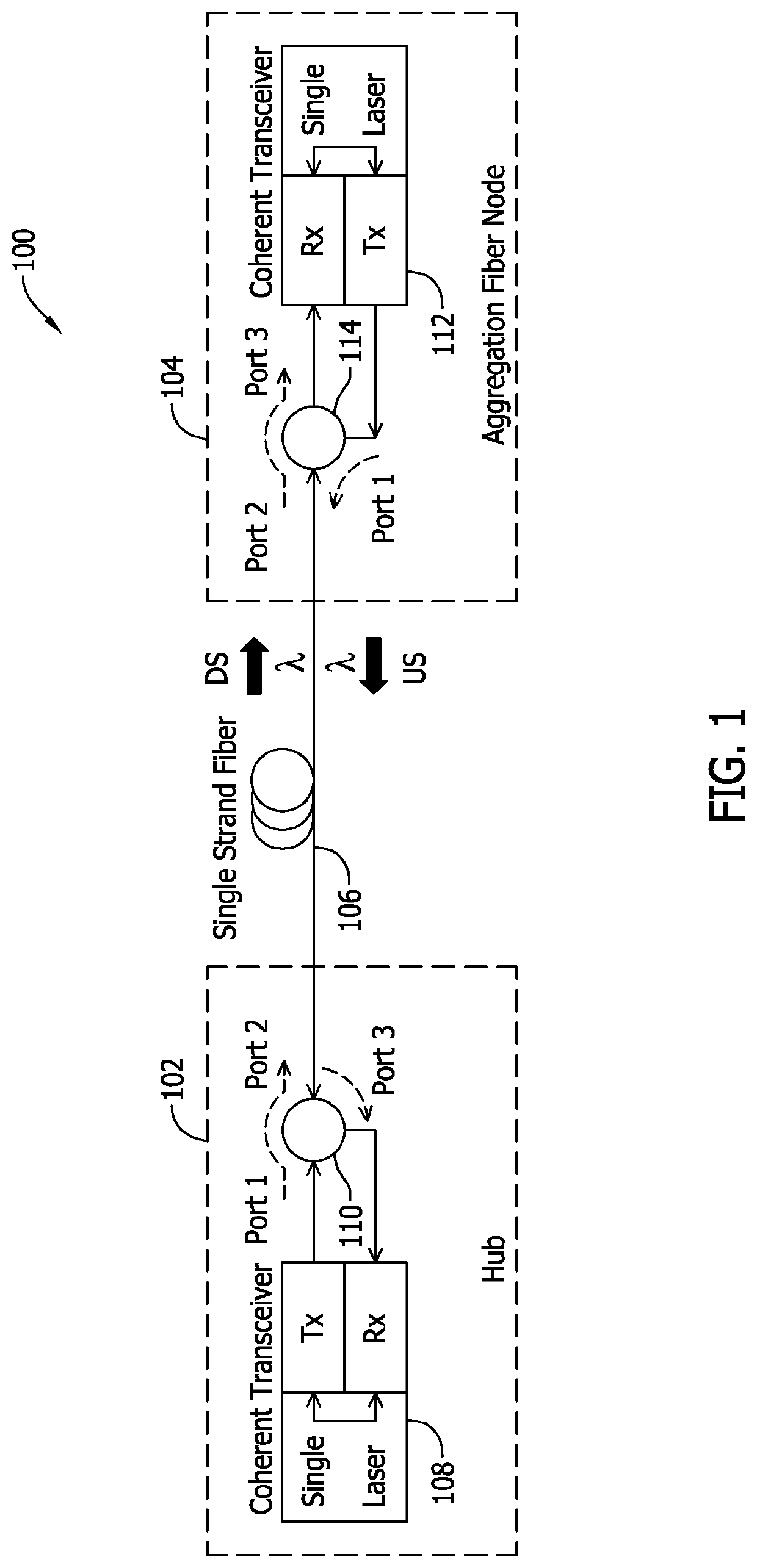
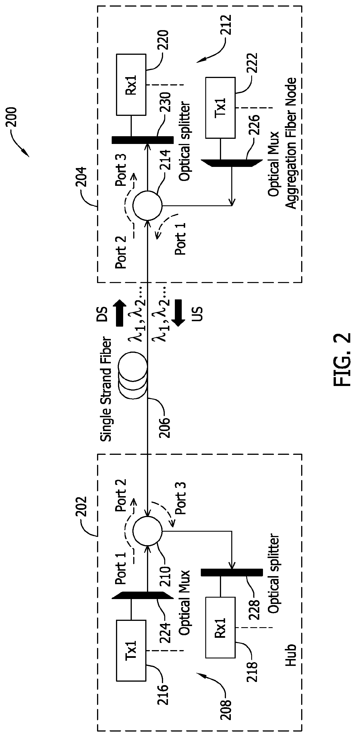
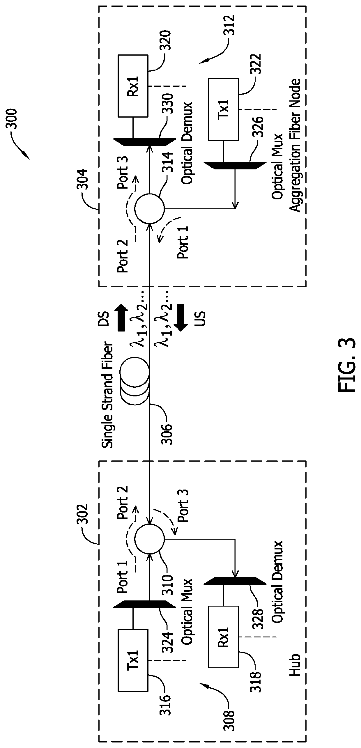
The patent describes a communication network that uses coherent optics to transmit data between devices. The network includes optical components such as optical fibers and optical circulators to separate and transmit the optical signals. The network can transmit and receive optical signals simultaneously using the same optical components. The network also includes optical transmitters and receivers that use different wavelengths of light to transmit and receive the optical signals. The network can be used in a full duplex communication mode, where both the transmitter and receiver simultaneously transmit and receive optical signals. The network can also include a test system to measure the performance of the network. The patent also describes different fiber connector structures and the effect of multipath interference on the network. Overall, the patent provides a technical solution for improving the efficiency and reliability of optical communication networks.

Problems solved by technology

Most network operators have very limited fiber available between the headend (HE) / hub and the fiber node to use for data and video services, often only just 1-2 fiber strands.
One way is to add more fiber between the HE / hub and the fiber node, but retrenching is costly and time consuming, so return on investment (RoI) makes this option unattractive.
Coherent optics technology is becoming common in the subsea, long-haul, and metro networks, but has not yet been fully integrated into the access networks.
However, existing coherent transceiver designs have been unable to fully leverage the capabilities of bidirectional transmission.
In particular, conventional implementations of single laser sources for both the transmitter and the local oscillator (LO) result in significant crosstalk that has prevented bidirectional transmission.

Method used


Image

  • Systems and methods for full duplex coherent optics
  • Systems and methods for full duplex coherent optics
  • Systems and methods for full duplex coherent optics

Examples


Embodiment Construction

[0083]In the following specification and claims, reference will be made to a number of terms, which shall be defined to have the following meanings.

[0084]The singular forms “a,”“an,” and “the” include plural references unless the context clearly dictates otherwise.

[0085]“Optional” or “optionally” means that the subsequently described event or circumstance may or may not occur, and that the description includes instances where the event occurs and instances where it does not.

[0086]As used herein, unless specified to the contrary, “modem termination system,” or “MTS” may refer to one or more of a cable modem termination system (CMTS), an optical network terminal (ONT), an optical line terminal (OLT), a network termination unit, a satellite termination unit, and / or other termination devices and systems. Similarly, “modem” may refer to one or more of a cable modem (CM), an optical network unit (ONU), a digital subscriber line (DSL) unit / modem, a satellite modem, etc.

[0087]As used herein...


PUM


Abstract

A full duplex communication network includes an optical transmitter end having a first coherent optics transceiver, an optical receiver end having a second coherent optics transceiver, and an optical transport medium operably coupling the first coherent optics transceiver to the second coherent optics transceiver. The first coherent optics transceiver is configured to simultaneously transmit a downstream optical signal and receive an upstream optical signal. The second coherent optics transceiver is configured to simultaneously receive the downstream optical signal from the first coherent optics transceiver and transmit the upstream optical signal first coherent optics transceiver. At least one of the downstream optical signal and the upstream optical signal includes at least one coherent optical carrier and at least one non-coherent optical carrier.

Description

CROSS REFERENCE TO RELATED APPLICATIONS[0001]This application is a continuation in part of U.S. application Ser. No. 16 / 274,152, filed Feb. 12, 2019. U.S. application Ser. No. 16 / 274,152 is a continuation in part of U.S. application Ser. No. 16 / 198,396, filed Nov. 21, 2018. U.S. application Ser. No. 16 / 198,396 claims the benefit of and priority to U.S. Provisional Patent Application Ser. No. 62 / 589,121, filed Nov. 21, 2017, and to U.S. Provisional Patent Application Ser. No. 62 / 636,249, filed Feb. 28, 2018. U.S. application Ser. No. 16 / 274,152 also claims the benefit of and priority to U.S. Provisional Patent Application Ser. No. 62 / 629,555, filed Feb. 12, 2018. The present application also claims the benefit of and priority to U.S. Provisional Patent Application Ser. No. 62 / 719,072, filed Aug. 16, 2018. All of these applications are incorporated herein by reference in their entireties.BACKGROUND[0002]The field of the disclosure relates generally to communication networks, and more ...

Claims


Application Information

Patent Timeline
IPC IPC(8): H04J14/00H04B10/43H04L5/14H04J14/02H04B10/25
CPCH04L5/14H04B10/43H04J14/0234H04B10/2503H04J14/0236H04J14/002H04B10/40H04J14/0307H04B10/2589
Inventor JIA, ZHENSHENGCAMPOS, LUIS ALBERTOWANG, JINGXU, MUZHANG, HAIPENGKNITTLE, CURTIS DEAN
Owner CABLE TELEVISION LAB
Learn More