
Electric parking brake device

a technology of electric parking brake and electric motor, which is applied in the direction of fluid-actuated drum brake, braking system, transportation and packaging, etc., can solve the problems of inconvenient assembly of the plurality of parts, inability to efficiently cope with the inability to accurately control the temperature of the drum, so as to achieve the effect of efficient thermal expansion of the drum, simple structure and more precision

Active Publication Date: 2020-02-20
HYUNDAI MOBIS CO LTD
View PDF0 Cites 11 Cited by
  • Summary
  • Abstract
  • Description
  • Claims
  • Application Information

AI Technical Summary

Benefits of technology

The present invention provides an electronic parking brake device with several technical effects. Firstly, the device has a simpler structure as it includes a gear unit, rotating rod, push rod, and clutch unit coaxially connected and fastened to one housing, avoiding the need for multiple parts. Secondly, the device allows for a more precise adjust function to constantly maintain a gap between the park brake shoe and drum, using a load sensor to control the actuator. Thirdly, the device can flexibly compensate for changes in the gap with the drum due to thermal expansion or wear of the friction material, preventing degradation in adjustment precision. Overall, the invention helps to improve the efficiency and precision of electronic parking brakes.

Problems solved by technology

Also, an inconvenient process of assembling the plurality of parts to set positions needs to be performed in order to implement the adjust function in interconnection with moving line changes of the shoes and the operating lever for a parking brake.
Furthermore, since gap compensation is performed based on the gear of the adjustment nut, the precision is inevitably low, and an operation of reducing the length of the adjuster cannot be implemented, which makes it difficult to efficiently cope with thermal expansion of the drum.
Furthermore, the electronic parking brake device can omit an inconvenient process of assembling the parts to preset positions in order to implement the adjust function in connection with moving line changes of the shoes and the operating lever for the parking brake.

Method used


Image

  • Electric parking brake device
  • Electric parking brake device
  • Electric parking brake device

Examples


Embodiment Construction

[0040]The invention is described more fully hereinafter with reference to the accompanying drawings, in which embodiments of the invention are shown. This invention may, however, be embodied in many different forms and should not be construed as limited to the embodiments set forth herein. Rather, these embodiments are provided so that this disclosure is thorough, and will fully convey the scope of the invention to those skilled in the art. In the drawings, the size and relative sizes of layers and regions may be exaggerated for clarity. Like reference numerals in the drawings denote like elements.

[0041]Various advantages and features of the present invention and methods accomplishing thereof will become apparent from the following description of embodiments with reference to the accompanying drawings. However, the present invention is not be limited to the embodiments set forth herein but may be implemented in many different forms. The present embodiments may be provided so that th...


PUM


Abstract

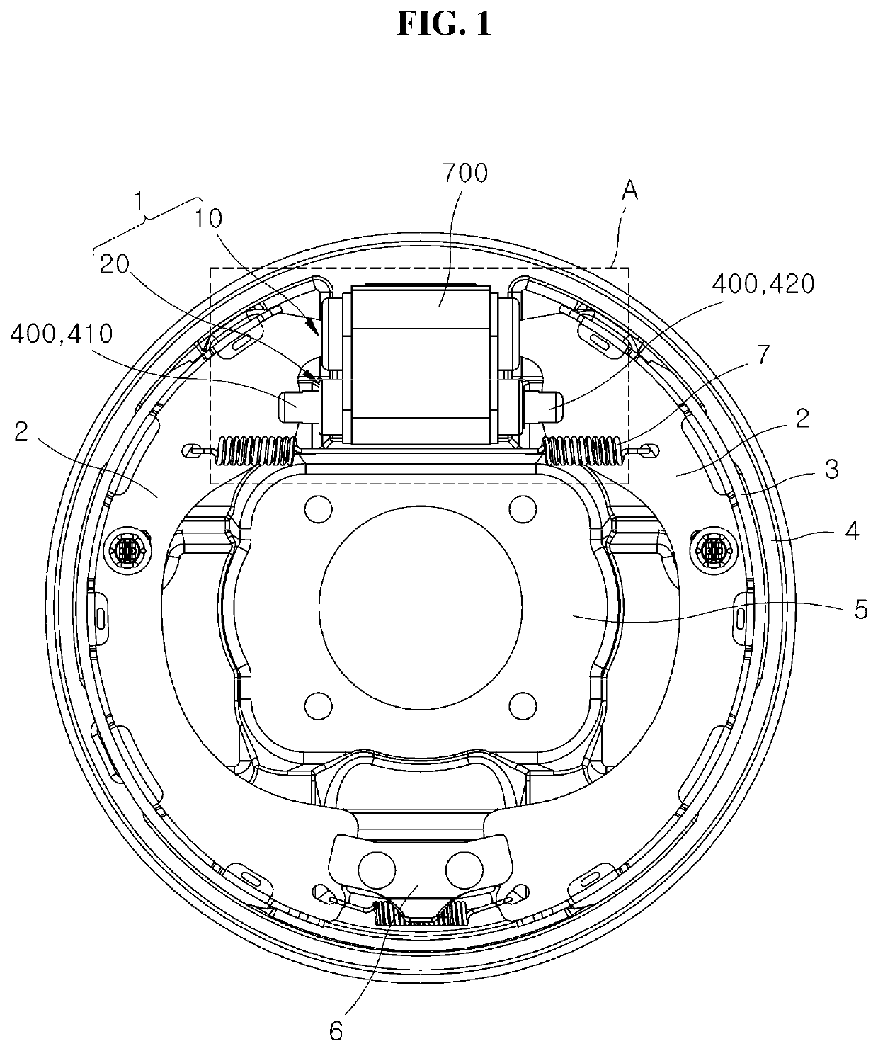
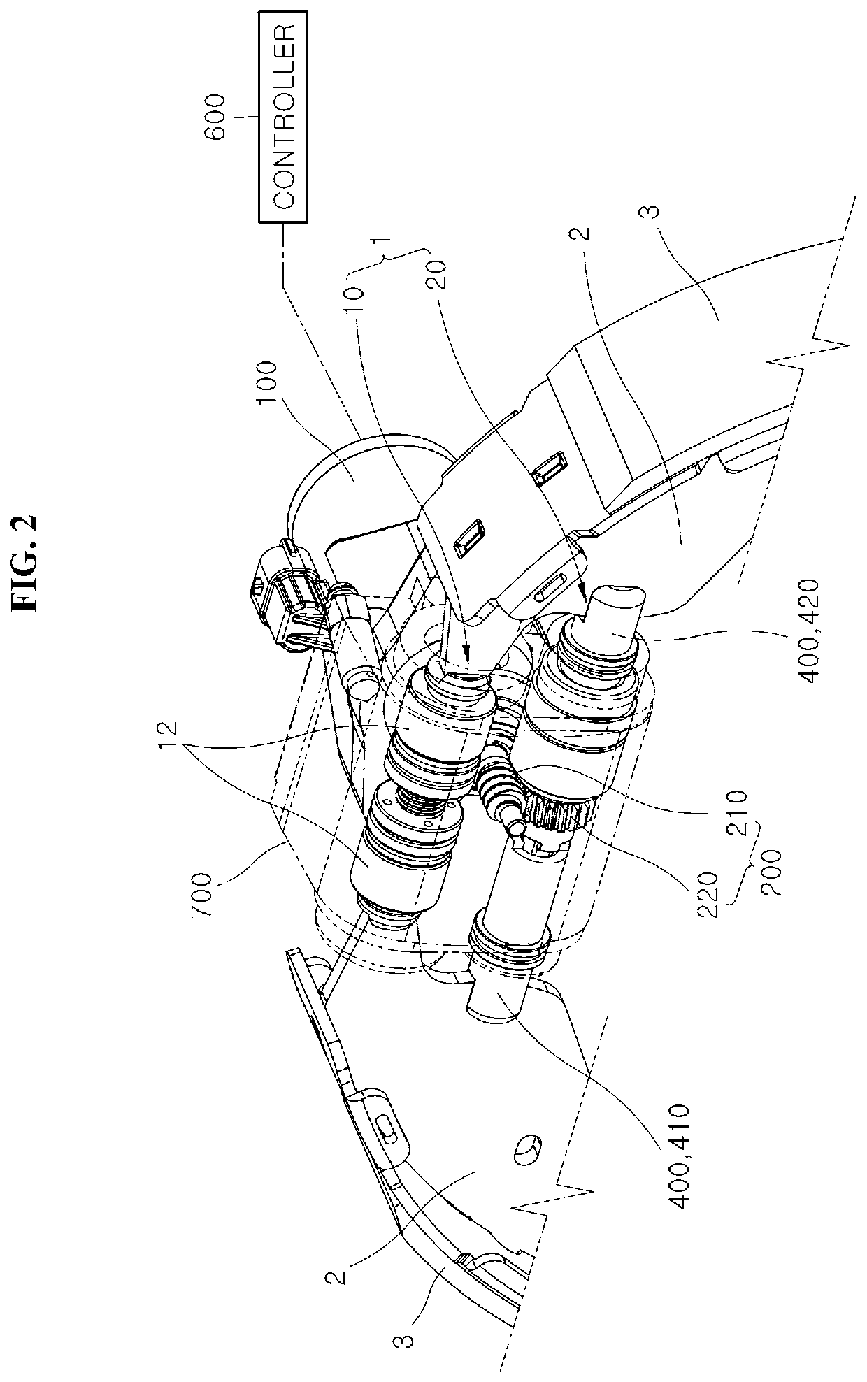
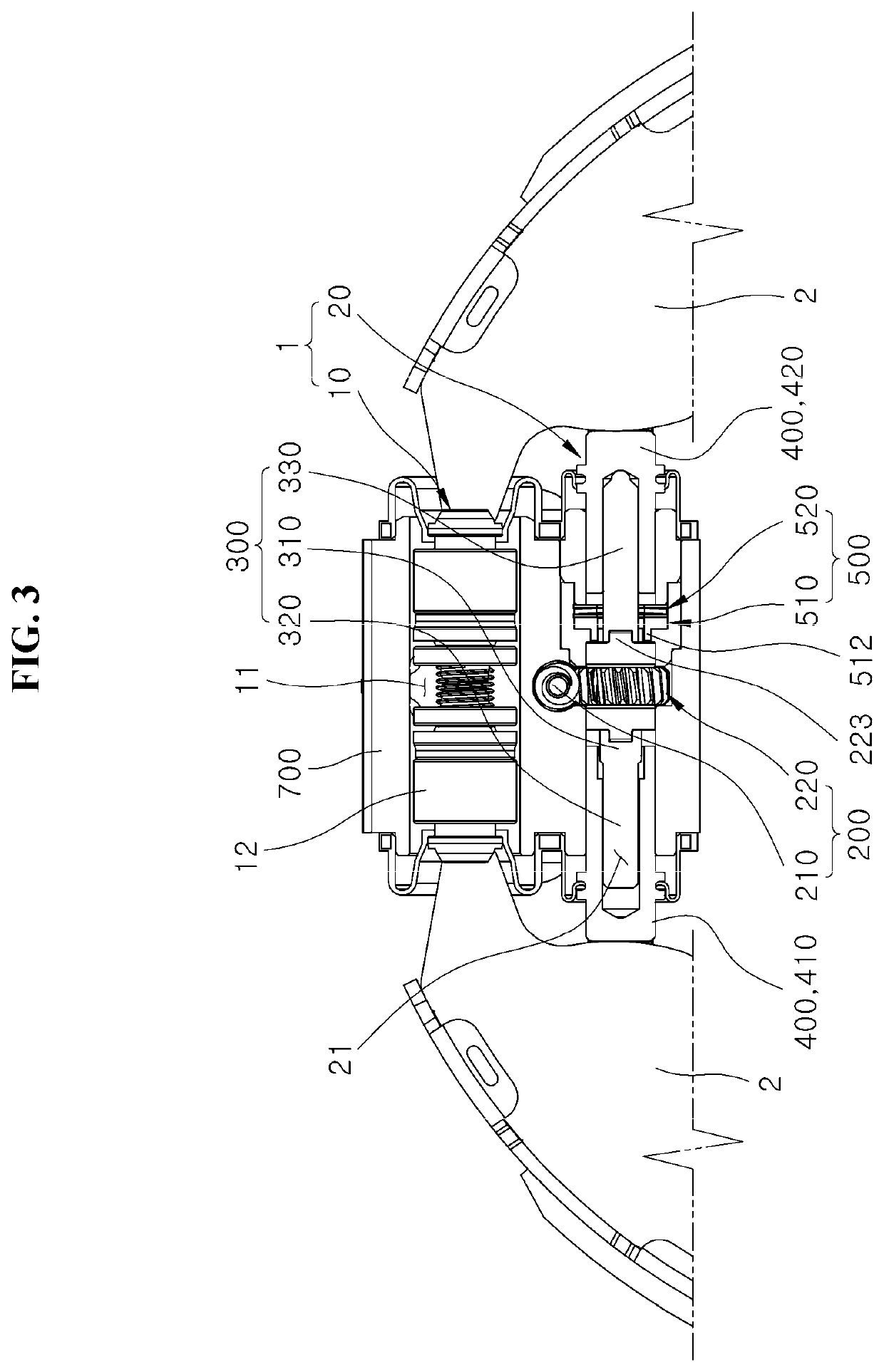
An electronic parking brake device may include: a gear unit driven by an actuator; a rotating rod connected to the gear unit; a push rod unit configured to pressurize one or more shoes while moved in connection with the rotating rod; a clutch unit disposed to interfere with a moving line of the gear unit, and configured to apply a rotational load to the gear unit while abutting on the gear unit, when the gear unit is rotated at a present angle; and a controller configured to control the operation of the actuator according to the load applied to the actuator.

Description

CROSS-REFERENCE TO RELATED APPLICATION[0001]This application claims priority from and the benefit of Korean Application No. 10-2018-0096268, filed on Aug. 17, 2018, which is hereby incorporated by reference for all purposes as if set forth herein.BACKGROUNDField[0002]Exemplary embodiments relate to an electronic parking brake device, and more particularly to an electronic parking brake device for braking a parked vehicle using an actuator.Discussion of the Background[0003]In general, a drum brake refers to a device that generates a braking force through friction with a drum rotating with a wheel. Specifically, the drum brake acquires a braking force by using hydraulic pressure (main braking) or rubbing a shoe having a friction material attached thereto against the drum using a cable connected to a parking brake lever (parking braking). The conventional drum brake includes the drum, a pair of shoes disposed on a back plate so as to face the inner circumferential surface of the drum a...

Claims


Application Information

Patent Timeline
Patent Type & Authority Applications(United States)
IPC IPC(8): B60T13/58F16D65/56H02K7/10
CPCF16D65/563B60T13/588H02K7/10F16H63/3416F16H63/345F16H63/3466B60T13/741H02K7/1166F16D51/14F16D65/48
Inventor CHOI, MOO JIN
Owner HYUNDAI MOBIS CO LTD
Learn More