Inertial hydrodynamic pump and wave engine

a hydrodynamic pump and wave engine technology, applied in the direction of energy supply, special-purpose vessels, vessel construction, etc., can solve the problems of reducing the pressure inside the uppermost, achieve the effect of reducing the heat from the “active” computational device, avoiding excessive heating of the computational device, and facilitating passive convective cooling

Active Publication Date: 2020-02-20
LONE GULL HLDG LTD
View PDF0 Cites 28 Cited by
  • Summary
  • Abstract
  • Description
  • Claims
  • Application Information

AI Technical Summary

Benefits of technology

[0010]A preferred embodiment is characterized by a waterplane area that is at least five times greater than the average horizontal cross-sectional area of the upper surface of the resting water partially enclosed within the tube. A preferred embodiment is characterized by a buoy that is quasi-spherical especially in the region of a resting waterline. A preferred embodiment is free-floating, unmoored, self-propelled, and possessing computing devices that are used to process computational tasks transmitted to it by a satellite, or by other electromagnetically- or optically-encoded signals, so that it can perform computational tasks on demand and / or autonomously, far from any shore and / or in the midst of waves that tend to be more energetic than those found near shore. Another preferred embodiment promotes the growth of fish, macroalgae, microalgae, bivalves, and / or other organisms, within the reservoir of the device, sometimes by using a portion of the energy that it generates to generate light to support their growth and / or to propel the device to locations offering favorable environmental resources. Another preferred embodiment captures minerals dissolved in seawater by using the pumping action of the embodiment to drive water at elevated pressure through or adjacent to an adsorbent or absorbent capture medium. Another preferred embodiment uses the water-pumping action of the embodiment to circulate water to create a hospitable and waste-free environment for fish captive within a reservoir of the embodiment. Finally, another preferred embodiment uses its water-pumping action to propel seawater skywardly to increase the number of cloud nucleation sites in the air above the embodiment.
[0272]An embodiment of the current disclosure utilizes and / or incorporates computing devices that consume at least a portion of the electrical energy generated by the embodiment in response to wave action in order to perform computations transmitted to it from a remote source (i.e., from a source not physically—rigidly or flexibly—connected to the embodiment) such as via encoded electromagnetic transmissions from a satellite or other remote antenna of executable codes and / or data and / or programs and / or instructions. A substantial portion of the electrical power generated by the embodiment in response to wave action is used to energize the embodiment's cluster(s) of computers, at least some of the time.

Problems solved by technology

The resulting disparity in the movements of the tapered tube and the water therein tends to cause a reduction in the pressure inside an uppermost portion of the tapered tube, and, in some embodiments, causes air to be drawn into the tube from above.

Method used


Image

  • Inertial hydrodynamic pump and wave engine
  • Inertial hydrodynamic pump and wave engine
  • Inertial hydrodynamic pump and wave engine

Examples


embodiment 100

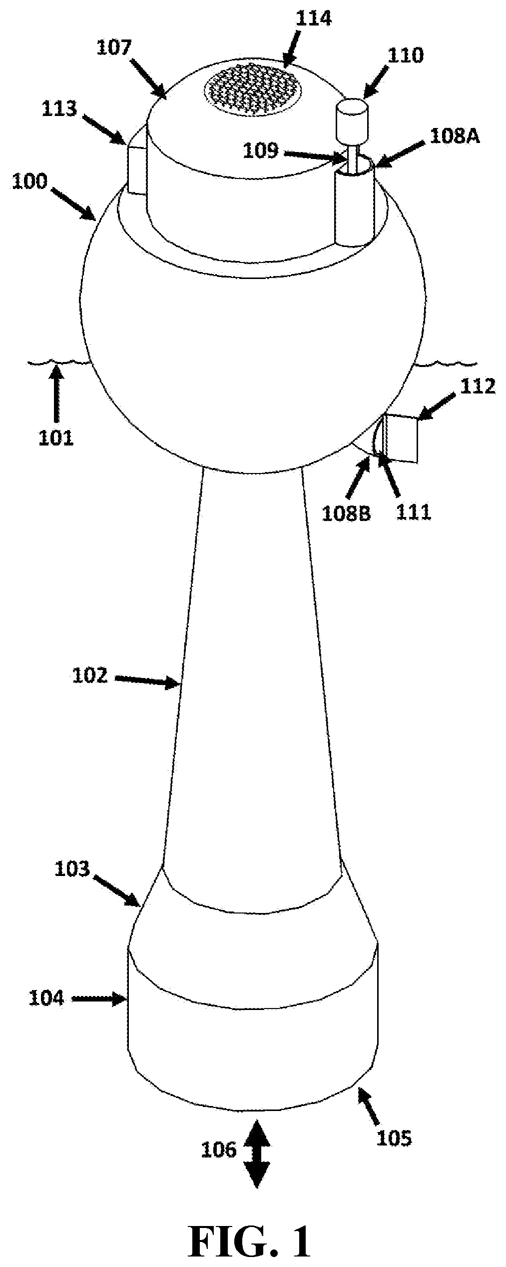
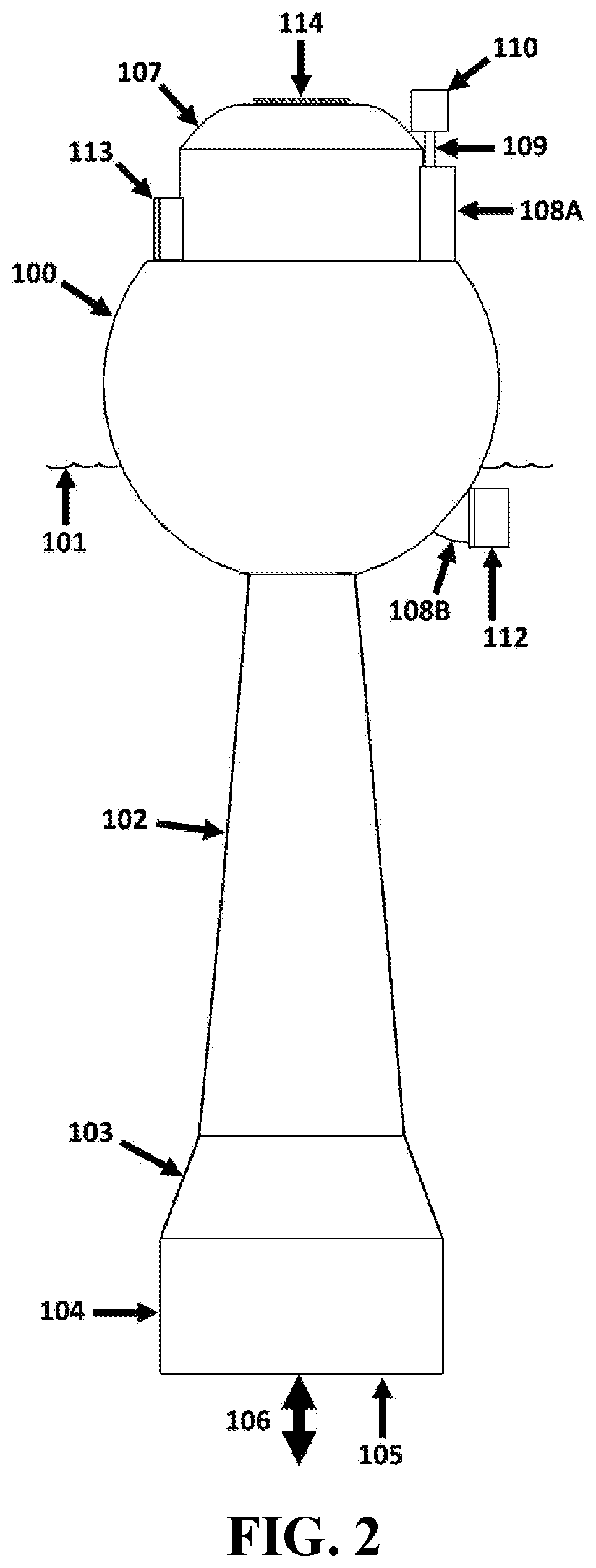
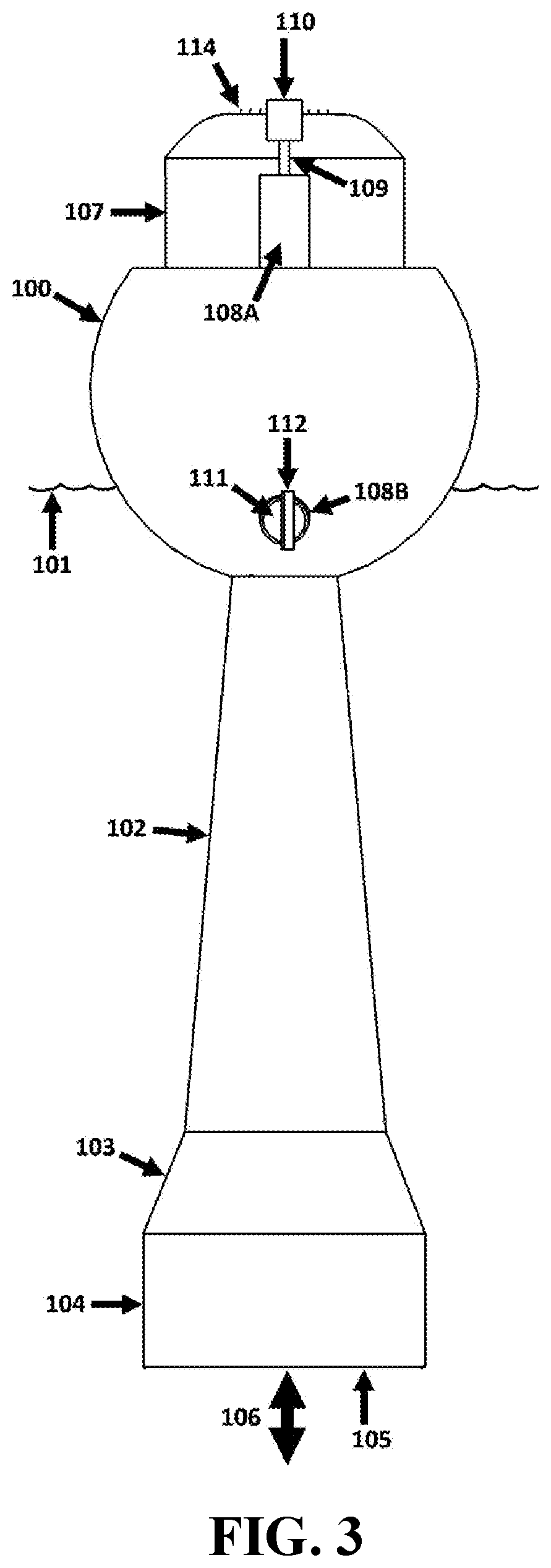
[0818]The buoyant embodiment 100 floats adjacent to an upper surface 101 of a body of water over which waves tend to pass. The embodiment incorporates a tapered inertial water tube 102-104 characterized by approximately circular cross-sections with respect to sectional planes normal to a (nominally vertical) longitudinal axis of the tube, and / or normal to an axis of inner-tube fluid flow, i.e., characterized by approximately “flow-normal cross-sectional shapes and / or areas”. An upper first portion 102 of the inertial water tube 102-104 has a frusto-conical shape (having circular flow-normal cross-sectional areas that increase in diameter with respect to increasing depths within the body of water 101 on which the embodiment floats). A second portion 103 of the inertial water tube 102-104 has a frusto-conical shape of a greater included angle. And, a bottom-most third portion 104 of the inertial water tube 102-104 is approximately cylindrical (having circular flow-normal cross-section...

embodiment 200

[0839]The buoyant embodiment 200 floats adjacent to an upper surface 201 of a body of water over which waves tend to pass. The embodiment incorporates an inertial water tube 202-203 comprised of both convex (e.g., 203) and concave (e.g., 202) tubular segments. A lower mouth 204 allows water to move 205 into and out from the interior of the inertial water tube 202-203. And, an upper mouth (not visible and inside the embodiment) of the inertial water tube 202-203 allows water to be ejected up and out of the inertial water tube, and into a water reservoir 206, when the water inside the inertial water tube rises fast enough and / or far enough. A portion of the gravitational potential energy and kinetic energy of the water ejected from the upper mouth of the inertial water tube 202-203 is preserved through the capture of a portion of that water in the water reservoir 206 which is positioned above the surface 201 of the body of water to which it will return.

[0840]A portion of the water tra...

embodiment 300

[0883]As the embodiment 300 moves up and down in response to waves traveling across the surface 301 of the body of water on which it floats, water within the embodiment's inertial water tube 302 tends to oscillate in a direction approximately parallel to a longitudinal axis of the inertial water tube, occasionally ejecting water from tubes (not visible) and upper mouths and / or apertures (not visible) incorporated within and / or at an upper end of the inertial water tube 302. Water ejected from the top of the inertial water tube 302 enters one of the four water reservoirs 305-308 at an approximately tangential orientation to each respective water reservoir's radially-symmetrical interior, thereby tending to induce in the water therein a swirling motion.

[0884]Water within each water reservoir 309-312 flows back to the body of water 301 through a respective effluent pipe e.g., 313 and 314, each effluent pipe of which is oriented so as to release and / or discharge its effluent in an appro...


PUM


Abstract

A buoyant hydrodynamic pump is disclosed that can float on a surface of a body of water over which waves tend to pass. The pump incorporates an open-bottomed tube with a constriction. The tube partially encloses a substantial volume of water with which the tube's constriction interacts, creating and / or amplifying oscillations therein in response to wave action. Wave-driven oscillations result in periodic upward ejections of portions of the water inside the tube that can be collected in a reservoir that is at least partially positioned above the mean water level of the body of water, or pressurized by compressed air or gas, or both. Water within such a reservoir may return to the body of water via a turbine, thereby generating electrical power (making the device a wave engine), or else the device's pumping action can be used for other purposes such as water circulation, propulsion, or cloud seeding.

Description

CROSS-REFERENCES TO RELATED APPLICATIONS[0001]This application claims priority from U.S. Ser. No. 62 / 718,383, filed Aug. 14, 2018; U.S. Ser. No. 62 / 719,648, filed Aug. 18, 2018; U.S. Ser. No. 62 / 724,629, filed Aug. 30, 2018; 62 / 739,190, filed Sep. 29, 2018; U.S. Ser. No. 62 / 755,427, filed Nov. 3, 2018; U.S. Ser. No. 62 / 768,968, filed Nov. 18, 2018; U.S. Ser. No. 62 / 831,202, filed Apr. 9, 2019, incorporated by reference in their entireties.BACKGROUND[0002]Waves traveling across the surface of the sea tend to move relatively slowly. Likewise, their oscillations tend to have relatively long periods, e.g., on the order of eight to twenty seconds. However, despite their relatively slow movement, waves tend to possess and / or manifest substantial amounts of energy. For these reasons, it is both desirable and difficult to extract energy from ocean waves. The device of the current invention efficiently extracts energy from ocean waves with a robust and relatively inexpensive design having fe...

Claims


Application Information

Patent Timeline
Patent Type & Authority Applications(United States)
IPC IPC(8): F03B17/06H02K7/18H02K44/08B63B22/18
CPCB63B2209/14H02K7/1823F03B17/06H02K44/085B63B22/18B63B2035/4466B63B35/44B63B1/048B63B2001/044F03B13/142F05B2240/93F03B13/145Y02E10/30
Inventor SHELDON-COULSON, GARTH ALEXANDERMOFFAT, BRIAN LEEPLACE, DANIEL WILLIAM
Owner LONE GULL HLDG LTD
Why Eureka
Try Eureka