Pressure sensors and methods of making pressure sensors

Active Publication Date: 2020-02-27
ROSEMOUNT AEROSPACE
View PDF0 Cites 0 Cited by
  • Summary
  • Abstract
  • Description
  • Claims
  • Application Information

AI Technical Summary

Benefits of technology

[0009]It is also contemplated that, in accordance with certain embodiments, the ceramic header body can include a pedestal shelf. The pedestal shelf can bound the transducer aperture. A pedestal can be seated on the pedestal shelf to support the MEMS pressure transducer and bound the fluid. The transducer aperture defined by the ceramic header body can have a fluid displacement structure. The fluid displacement structure can limit fluid volume within the transducer aperture for linearizing response of the MEMS pressure transducer. The fluid can include a low coefficient of thermal expansion fluid.
[0010]A differential pressure sensor includes a pressure sensor as described above with a second isolator diaphragm. The s

Problems solved by technology

The pressure transmitter itself is typically unsuited for direct measurement of the process fluid and is therefore generally located within the interior of steel housing containing a sense media, like pressure transfer oil, which

Method used


Image

  • Pressure sensors and methods of making pressure sensors
  • Pressure sensors and methods of making pressure sensors
  • Pressure sensors and methods of making pressure sensors

Examples


Embodiment Construction

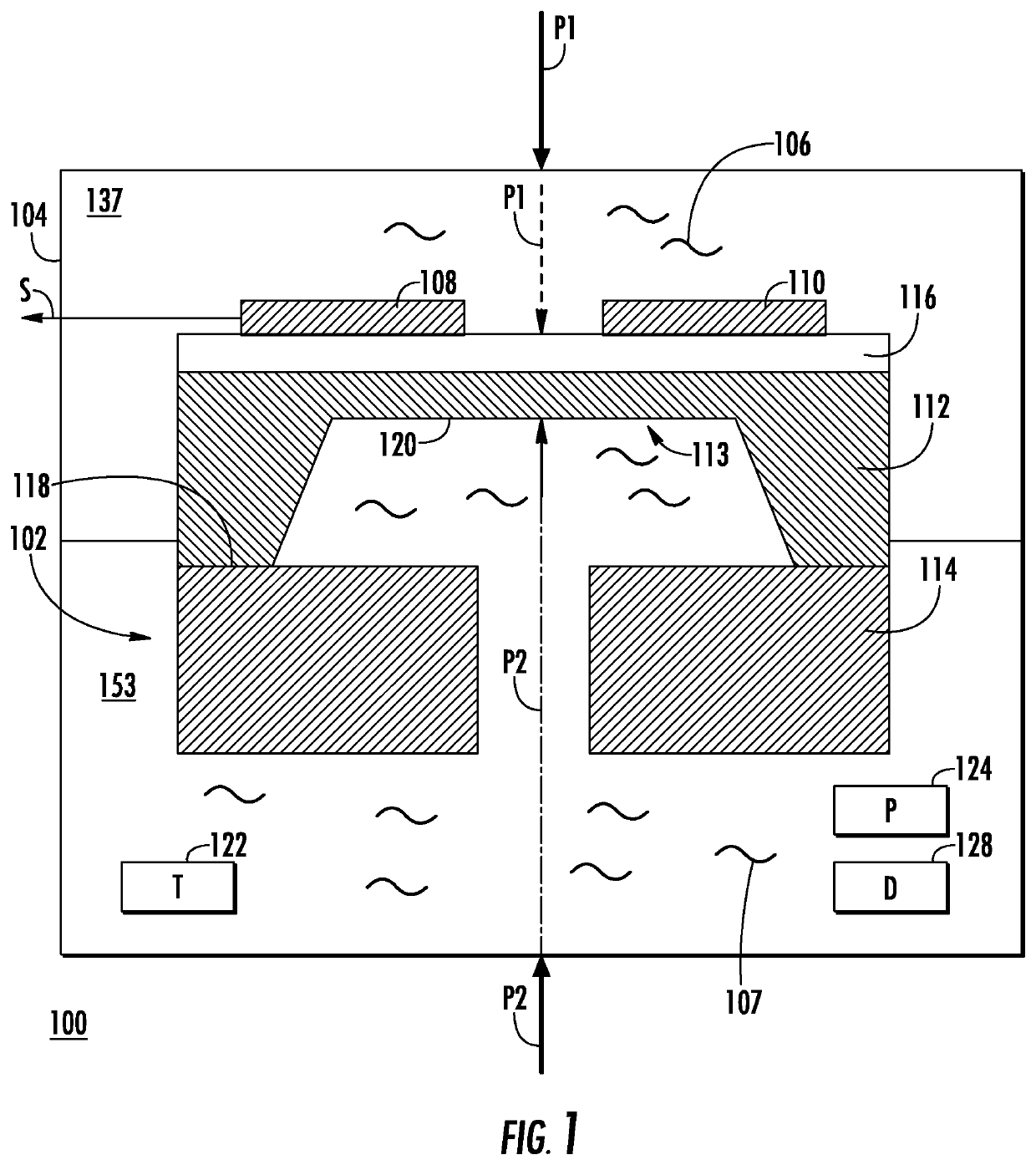
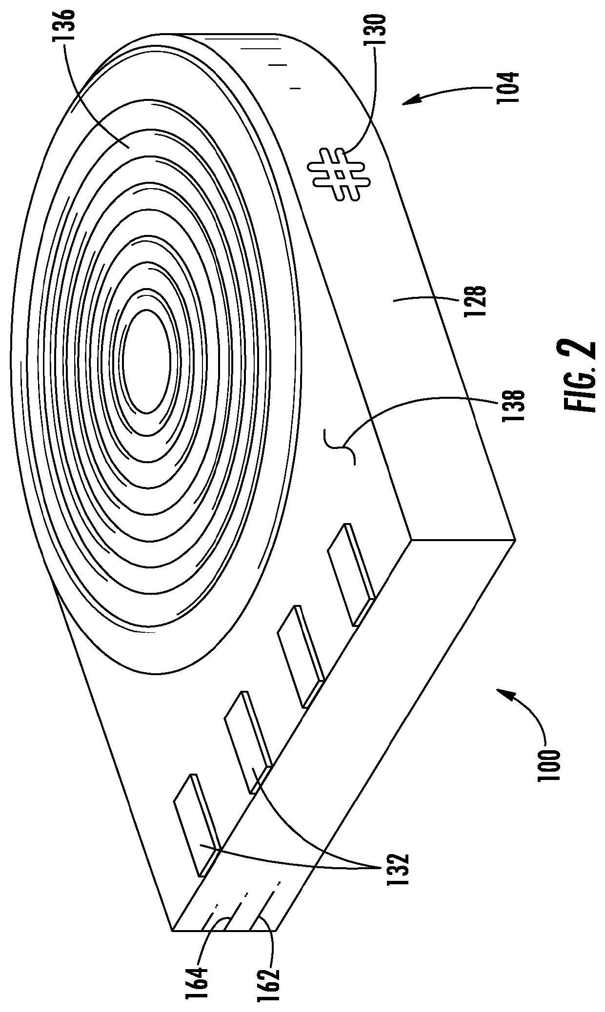
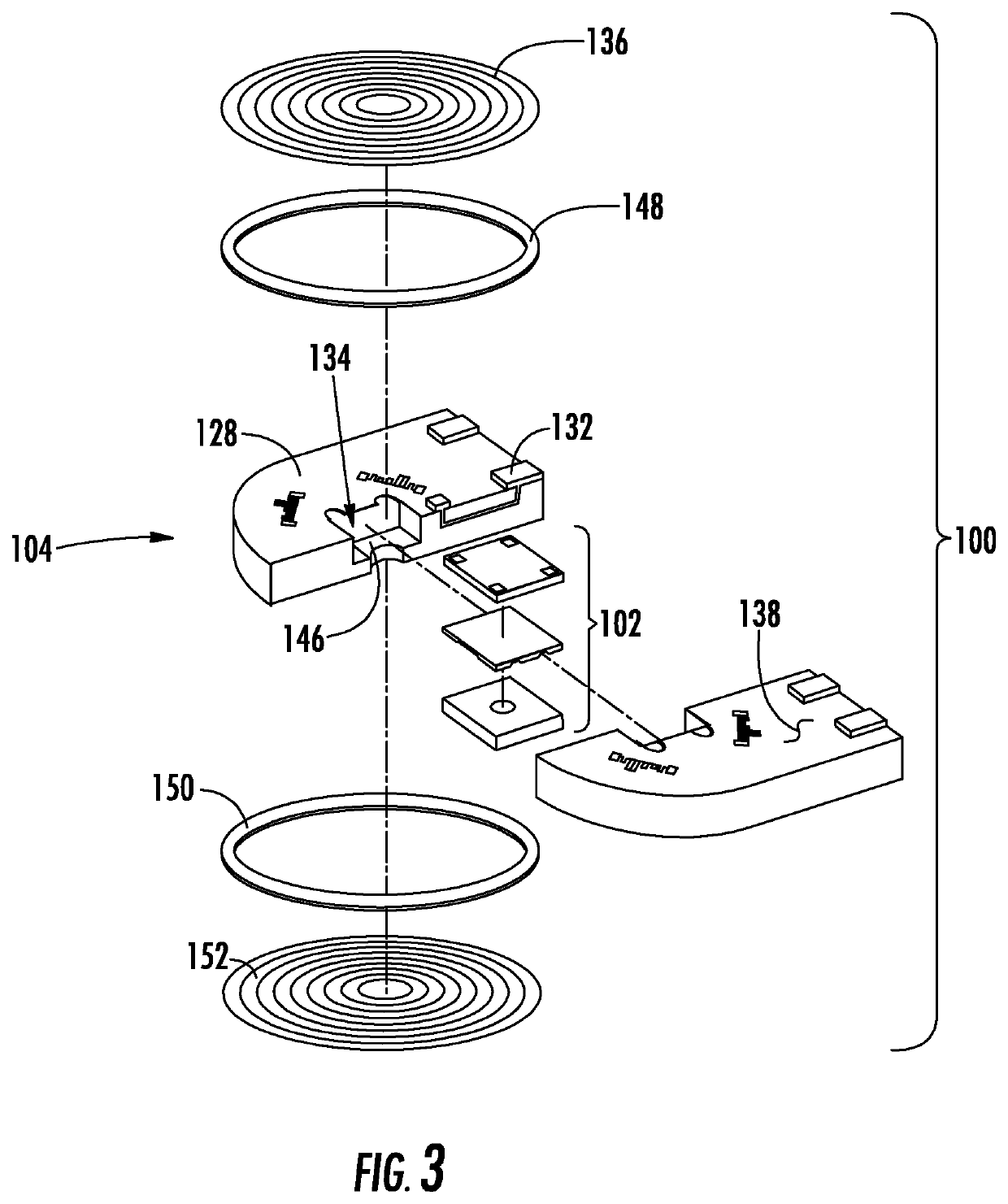
[0021]Reference will now be made to the drawings wherein like reference numerals identify similar structural features or aspects of the subject disclosure. For purposes of explanation and illustration, and not limitation, a partial view of an exemplary embodiment of pressure sensor in accordance with the disclosure is shown in FIG. 1 and is designated generally by reference character 100. Other embodiments of pressure sensors, differential pressure sensors, and methods of making pressure sensors in accordance with the disclosure, or aspects thereof, are provided in FIGS. 2-6, as will be described. The systems and methods described herein can be used sensing differential pressure, such as in gas turbine engines, though the present disclosure is not limited to gas turbine engines or to differential pressure sensing in general.

[0022]Referring to FIG. 1, pressure sensor 100 is shown. Pressure sensor 100 includes a microelectromechanical system (MEMS) pressure transducer 102 disposed wit...


PUM


Abstract

A pressure sensor includes a MEMS pressure transducer with a pressure sensing diaphragm and sensor elements, an isolator diaphragm spaced apart from the pressure sensing diaphragm, and a ceramic header body. The ceramic header body has an electrical conductor and transducer aperture with the MEMS pressure transducer supported therein. The isolator diaphragm is coupled to the to the MEMS pressure transducer by a fluid and is sealably fixed to the ceramic body. The ceramic header body bounds the fluid and the electrical conductor electrically connects the MEMS pressure transducer with the external environment. Differential pressure sensors and methods of making pressure sensors are also described.

Description

BACKGROUND OF THE INVENTION1. Field of the Invention[0001]The present disclosure relates to pressure sensors, and more particularly to pressure sensors having MEMS pressure transducers arranged within ceramic headers.2. Description of Related Art[0002]Pressure transmitters, such as those used in industrial settings to measure and monitor pressures of industrial process fluids, typically include a pressure transmitter. The pressure transmitter itself is typically unsuited for direct measurement of the process fluid and is therefore generally located within the interior of steel housing containing a sense media, like pressure transfer oil, which communicates pressure change in the external environment to the pressure transmitter. The pressure transmitter generates an electrical signal based on the pressure communicated by the sense media, which is indicative pressure in the external environment.[0003]Transmission of the electrical signal is typically accomplished by sensor leads. The ...

Claims


Application Information

Patent Timeline
IPC IPC(8): G01L13/02G01L19/00G01L19/06
CPCG01L19/0645G01L13/026G01L19/0084G01L13/025G01L19/0046G01L19/0076
Inventor SANDEN, CHRISTOPHERMCTIGHE, JAMES JOSEPHHUYNH, CUONG THO
Owner ROSEMOUNT AEROSPACE
Why Eureka
Try Eureka