Check patentability & draft patents in minutes with Patsnap Eureka AI!

Spad-based lidar system

Active Publication Date: 2020-02-27
ROBERT BOSCH GMBH
View PDF5 Cites 2 Cited by
  • Summary
  • Abstract
  • Description
  • Claims
  • Application Information

AI Technical Summary

Benefits of technology

The present invention relates to a lidar system that uses background light to improve its detection of objects. The invention takes advantage of the fact that background light is more likely to be polarized horizontally, which can be easily distinguished from reflected light. This allows for improved differentiation between background light and reflected light, resulting in improved optical signal-to-noise ratio and increased range of the lidar system. Additionally, the invention reduces the complexity and cost of the system by using a standard filter to reduce the effect of background light and by improving the microstructuring of a semiconductor material. The invention also ensures better eye safety and reduces the amount of light emitted. Finally, the invention improves the positioning of the measuring window in time to better distinguish light components that strike both photon detectors simultaneously.

Problems solved by technology

In particular, a SPAD may be so sensitive that background light in the area of the scanned object may have an interfering effect.
The LIDAR system may thus be complicated and expensive.

Method used


Image

  • Spad-based lidar system
  • Spad-based lidar system
  • Spad-based lidar system

Examples


Embodiment Construction

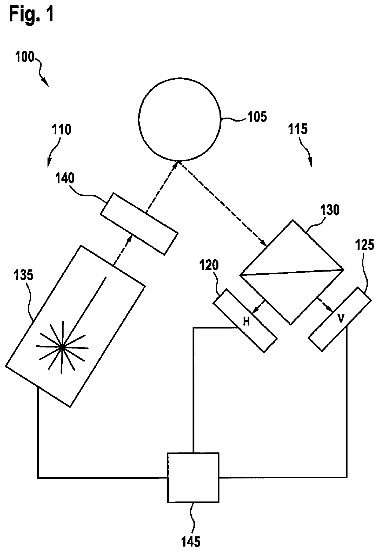
[0026]FIG. 1 shows a schematic configuration of a LIDAR system 100. LIDAR system 100 is configured for optically determining a direction or a distance of an object 105. LIDAR system 100 may be used in particular for scanning the surroundings of a motor vehicle. Object 105 may involve another road user or another vehicle, for example.

[0027]The scanning by a LIDAR system generally takes place with the aid of a light beam that is swiveled and / or rotated as a function of time. Alternatively, a so-called solid-state system or a flash LIDAR system may also be used. In both systems no moving parts are used, and the field of view (FOV) as a whole is illuminated. In the schematic illustration in FIG. 1, a fixed measuring range is assumed for the sake of simplicity.

[0028]LIDAR system 100 includes a transmitting device 110 for emitting light and a receiving device 115 for receiving light, which in particular has previously been emitted by transmitting device 110 and reflected on object 105. Fo...


PUM


Abstract

A LIDAR system includes a transmitting device for light; a receiving device for light, including a first and a second photon detector; and an evaluation device that is configured for determining a time period between the emission of light with the aid of the transmitting device and the incidence at the receiving device of the light reflected on an object. The transmitting device is configured for emitting a superimposition of horizontally and vertically polarized light; the first photon detector is configured for detecting only horizontally polarized light, and the second photon detector is configured for detecting only vertically polarized light; in addition, the evaluation device is configured for determining the time period, based on light that is incident on both photon detectors within a predetermined interval.

Description

FIELD OF THE INVENTION[0001]The present invention relates to a light detection and ranging (LIDAR) system for distance determination with the aid of optical scanning. In particular, the present invention relates to a LIDAR system that includes a single-photon avalanche detector (SPAD).BACKGROUND INFORMATION[0002]Present LIDAR systems are made up of a transceiver for laser light. The transmitting device transmits continuous wave (CW)-modulated or pulsed, generally infrared, laser light in the transmission direction. When this light strikes a moving or stationary object, for example a motor vehicle that is traveling or stopped, or a pedestrian, it is reflected back in the direction of the receiving unit. When the time difference between the point in time of transmission and the point in time of reception is evaluated in a detector (time of flight (TOF) method), a conclusion may be drawn concerning the distance traveled by the photons of the laser light, and thus, the distance from the...

Claims


Application Information

Patent Timeline
IPC IPC(8): G01S17/42G01S7/499G01S17/10G01S7/4861G01S7/4865G01S17/18G01S17/931
CPCG01S17/18G01S7/499G01S17/42G01S7/4861G01S7/4865G01S7/4876G01S7/493G01S17/931
Inventor HOLLECZEK, ANNEMARIEPETERSEIM, TOBIAS
Owner ROBERT BOSCH GMBH
Features
  • R&D
  • Intellectual Property
  • Life Sciences
  • Materials
  • Tech Scout
  • Unparalleled Data Quality
  • Higher Quality Content
  • 60% Fewer Hallucinations
Learn More