Methods and Apparatus for Generating Mid-Infrared Frequency Combs

a technology of infrared laser and comb, which is applied in the direction of laser details, active medium materials, instruments, etc., can solve the problems of limited simultaneous spectral coverage of the entire fingerprint region, limited spectral resolution and measurement time, and long-distance propagation, so as to improve light conversion efficiency

Active Publication Date: 2020-02-27
US REPRESENTED BY SEC OF COMMERCE +1
View PDF0 Cites 3 Cited by
  • Summary
  • Abstract
  • Description
  • Claims
  • Application Information

AI Technical Summary

Benefits of technology

[0010]One useful application for mid-IR frequency comb generating systems is dual comb spectroscopy. For these systems a second oscillator, broadening element, compression element, and comb generating element generates a second mid-IR frequency comb, and both combs are directed into an absorption cell containing a sample gas in such a manner as to cause dual frequency comb spectroscopy in the absorption cell. A MCT detector detects the light from the absorption cell.
[0011]Apparatus and methods are also provided for locking the frequency combs, using a reference near-IR oscillator for generating a reference near-IR signal, a filter for selecting a near-IR comb tooth from the first mid-IR frequency comb, a heterodyne element for heterodyning the reference near-IR signal and the near-IR comb tooth and generating a heterodyned signal, and a detector for detecting the mid-IR frequency comb. The detector also detects a beat note comprising the carrier envelope offset frequency of the mode-locked laser. A feedback mechanism locks the mid-IR frequency comb using the beat note and the heterodyned signal. This is especially useful in dual comb spectroscopy, where both mid-IR frequency combs

Problems solved by technology

However, the low brightness of FTIR thermal sources restricts focusability, long-distance propagation, and spectroscopic sensitivity, while the required mechanical delay of FTIR limits the combination of spectral resolution and measurement time.
Infrared laser spectroscopy has been pursued over a similar epoch, but simultaneous spectral coverage of the entire fingerprint region remains limited to radiat

Method used


Image

  • Methods and Apparatus for Generating Mid-Infrared Frequency Combs
  • Methods and Apparatus for Generating Mid-Infrared Frequency Combs
  • Methods and Apparatus for Generating Mid-Infrared Frequency Combs

Examples


Embodiment Construction

[0020]

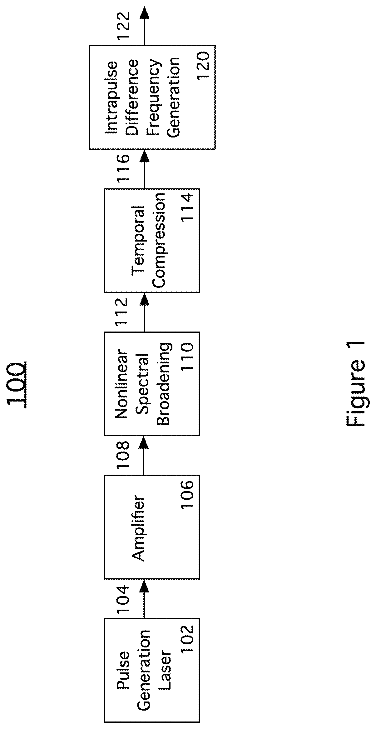
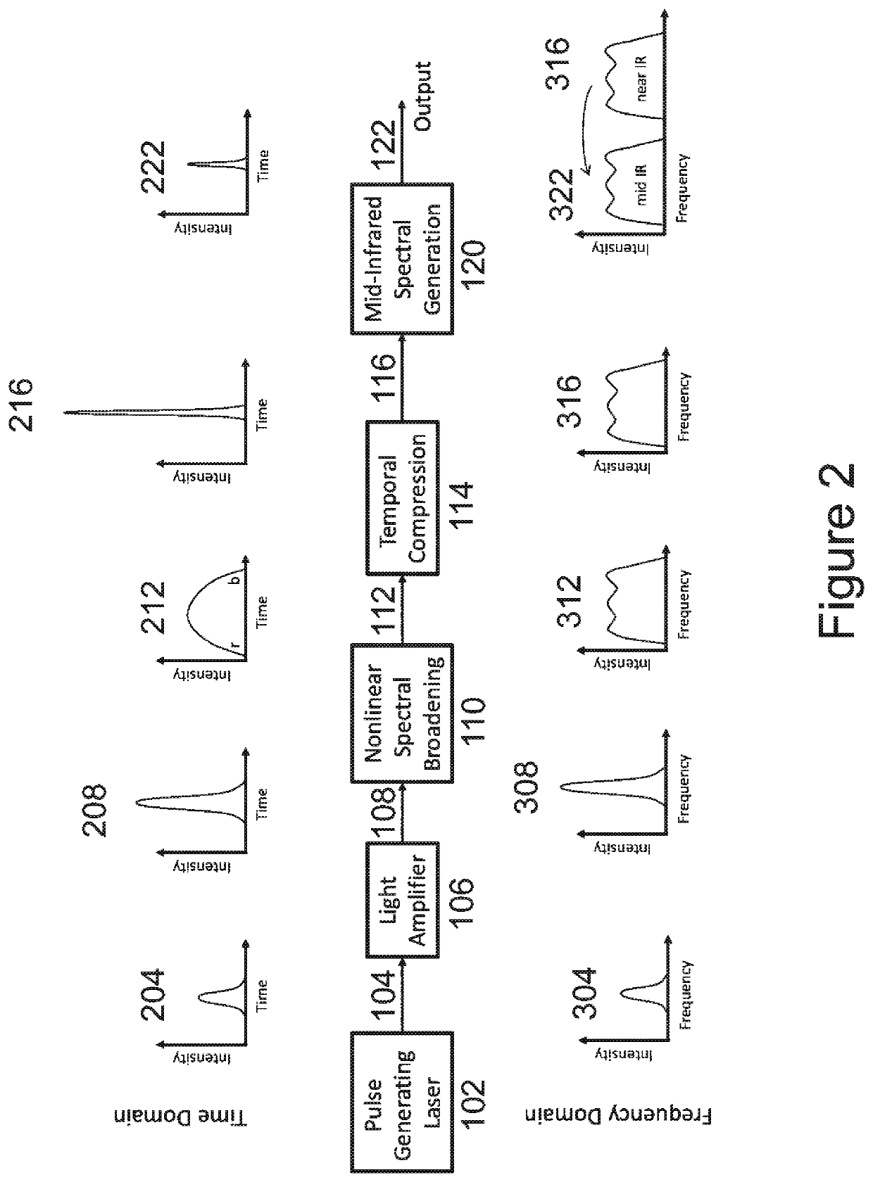
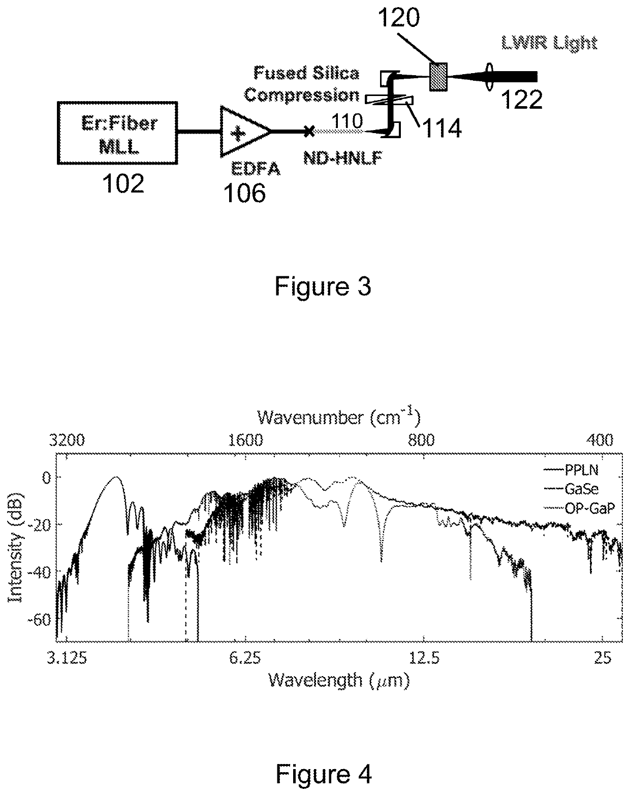
TABLE 1Ref. no.Element100, 300, 502, 504, 800Mid-IR comb generating systems102Pulse generating laser (near IR)104 / 204 / 304Near-IR pulses106Light amplifier108 / 208 / 308Amplified near-IR pulses110Nonlinear spectral broadening112 / 212 / 312Broadened pulses114Temporal compression116 / 216 / 316Few-cycle conditioned pulses117Off-axis parabolic mirror120Intrapulse difference frequency generation122 / 222 / 322Mid-IR frequency comb502First mid-IR comb source504Second mid-IR comb source506Absorption gas cell508FTS510MCT, reference spectrum512MCT detector530Bandpass filter602Optical isolator604Preamplifier606Amplifier608ND-HNLF610Chirped mirrors612Fused silica wedges800Mid-IR comb generating system801Lowpass filter802Comb804MCT Detector806DCS808Offset frequency beat810F0 lock parameter812Heterodyned lock parameter814Comb tooth816Stable laser signal818Photodetector820Heterodyned signal850Lock dual comb spectroscopy system

[0021]Table 1 provides reference numbers and associated elements of the inventio...


PUM


Abstract

Apparatus and methods for generating mid-IR frequency combs using intra-pulse DFG. A mode-locked pulse generation laser generates near-IR pulses which are amplified. The amplified pulses are spectrally broadened by a nonlinear element, for example a normal dispersion highly nonlinear fiber (ND-HNLF) to generate broadened pulses. The nonlinear spectral broadening element is a transparent dielectric material having a cubic nonlinear response. Broadened pulses are temporally compressed to generate short, high-power pulses which few-cycle conditioned pulses which are ready for the intrapulse DFG process. The DFG block generates a mid-IR comb by difference frequency generation. It might comprise an orientation patterned GaP (OP-GaP) crystal or a poled lithium niobate (PPLN) crystal.

Description

[0001]This invention was made with government support under grant numbers 70NANB14H095 awarded by NIST and 70NANB14H095 awarded by DOD / DARPA. The government has certain rights in the invention.BACKGROUND OF THE INVENTIONField of the Invention[0002]The present invention relates to the generation of infrared laser frequency combs. In particular, the present invention relates to apparatus and methods for generating mid-infrared laser frequency combs using intra-pulse difference frequency generation (DFG).Discussion of Related Art[0003]Infrared molecular spectroscopy is a powerful and ubiquitous technique for measuring the chemical makeup and structure in almost any state of matter. In particular, the inter-atomic degrees of freedom within a molecule or compound lead to series of discrete, vibrational states whose resonances are unique identifiers in the mid- to long-wave infrared spectrum spanning the molecular fingerprint region from approximately 6.7 to 20 μm (˜1500-500 cm−1). For th...

Claims


Application Information

Patent Timeline
IPC IPC(8): G02F1/35G02F1/355H01S3/16G02F1/365
CPCG02F1/3501H01S3/1671G02F1/3551G02F2001/3503G02F2203/56G02F1/365H01S3/0078H01S3/0092H01S3/0057H01S3/06758H01S3/09415H01S3/1608H01S3/1618H01S3/2391G02F1/3503
Inventor DIDDAMS, SCOTTTIMMERS, HENRYKOWLIGY, ABIJITH J.LIND, ALEXANDER JACOBPAPP, SCOTT
Owner US REPRESENTED BY SEC OF COMMERCE
Why Eureka
Try Eureka