Isolated DC/DC converter for controlling power flows between three DC terminals

a dc/dc converter and terminal technology, applied in the field of power electronics, can solve the problems of increased production costs, low power density, poor overall efficiency of the system, etc., and achieve the effect of preventing destabilization of the entire converter, reducing the port voltage, and no destabilization of the converter results

Active Publication Date: 2020-03-05
ROBERT BOSCH GMBH
View PDF13 Cites 3 Cited by
  • Summary
  • Abstract
  • Description
  • Claims
  • Application Information

AI Technical Summary

Benefits of technology

[0033]In the following text, the mode of operation of the converter is intended to be explained in even more detail based on concrete examples. In the case of a negative power at a series-interconnected port of the converter and an excessively high capacitor voltage at the capacitor of said port, the power fed to the capacitor must be reduced to effect a reduction in the port voltage. Correction terms for the power distributions of the individual cells are now determined by a superordinate converter (PAdiff,k, PBdiff,k and PCdiff,k). In order to prevent destabilization of the entire converter despite different cell powers of the individual converter cells, the sum of the cell-internal correction terms PAdiff,k+PBdiff,k=−PCdiff,k is compensated by means of the parallel-connected LV port. This is a further advantage when all converter cells are connected in parallel on the LV side or at the LV system. The LV system can thus also be used simultaneously to stabilize the individual cell powers by virtue of power differences between the individual cells being balanced.
[0034]This is possible, in particular, because, in contrast to the series-interconnected ports, an asymmetrical power distribution in the parallel-connected cell ports does not result in a change in the ratio between the respective port voltages and therefore no destabilization of the converter results. Such a stabilizing effect would not be able to be brought about using purely series-interconnected cells because three cell-internal port voltages would have to be regulated there but would have available only two degrees of freedom (port powers) for regulating the cell voltages. For this reason, for a stable operation of the described multi-port multi-cell converter, it is inevitable that at least one port of the converter cells is interconnected in parallel, via which the power differences between the cells can be balanced.

Problems solved by technology

This leads both to a poorer overall efficiency of the system and to increased production costs and low power density due to low system integration.

Method used


Image

  • Isolated DC/DC converter for controlling power flows between three DC terminals
  • Isolated DC/DC converter for controlling power flows between three DC terminals
  • Isolated DC/DC converter for controlling power flows between three DC terminals

Examples


Embodiment Construction

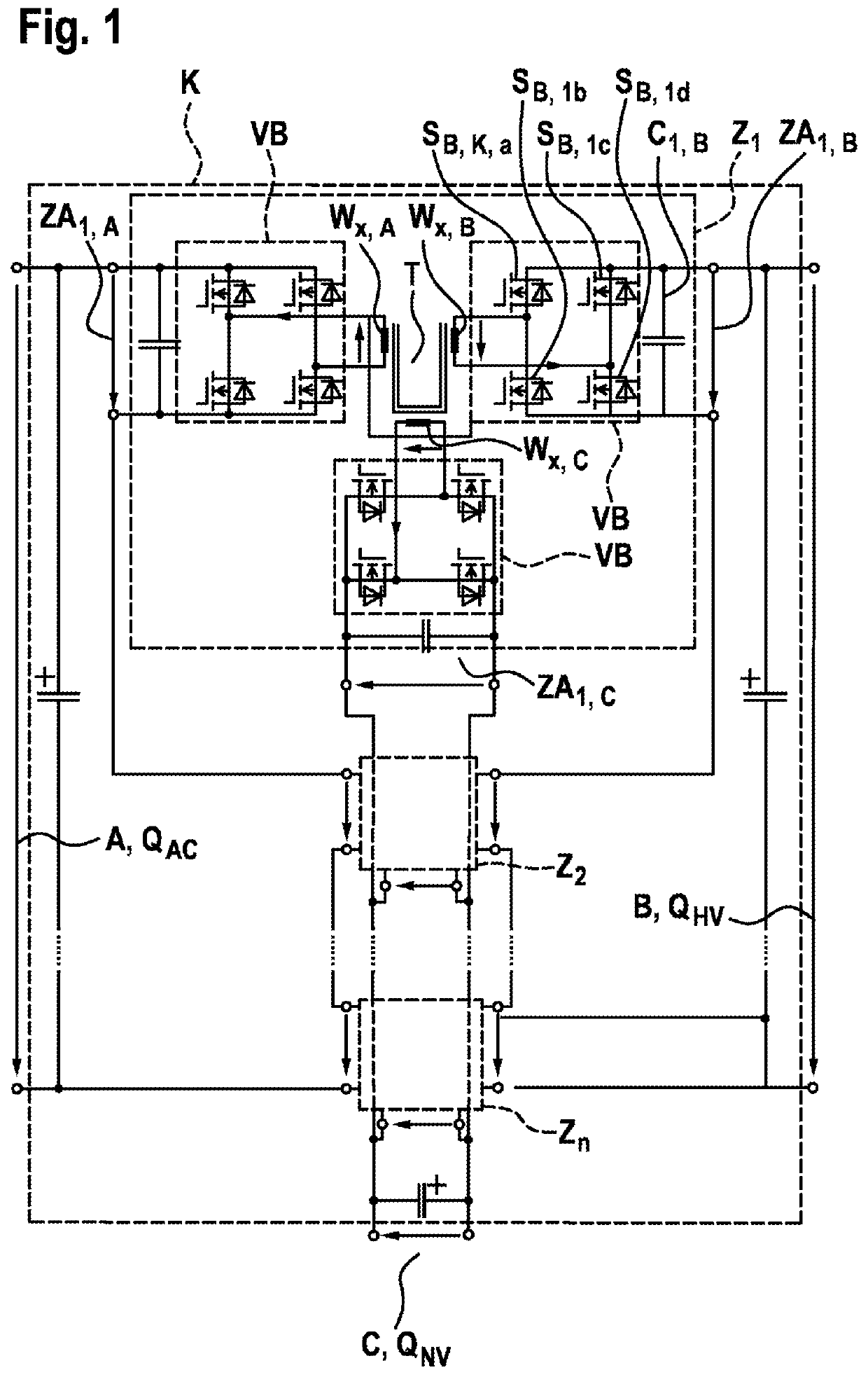
[0044]The presented multi-port multi-cell topology of a converter K makes omnidirectional power flow possible between three DC-isolated DC voltage sources. Said topology preferably consists of a plurality of identical three-port cells Z1,2,n, which are interconnected either in series or in parallel depending on the level of the applied port voltages of the overall system. FIG. 1 shows the converter K having a plurality of cells Z1,2,n. The converter K has three terminals A, B and C, wherein terminal A is associated with an electricity system QAC, terminal B is associated with a high-voltage system QHV and terminal C is associated with a low-voltage system QNV.

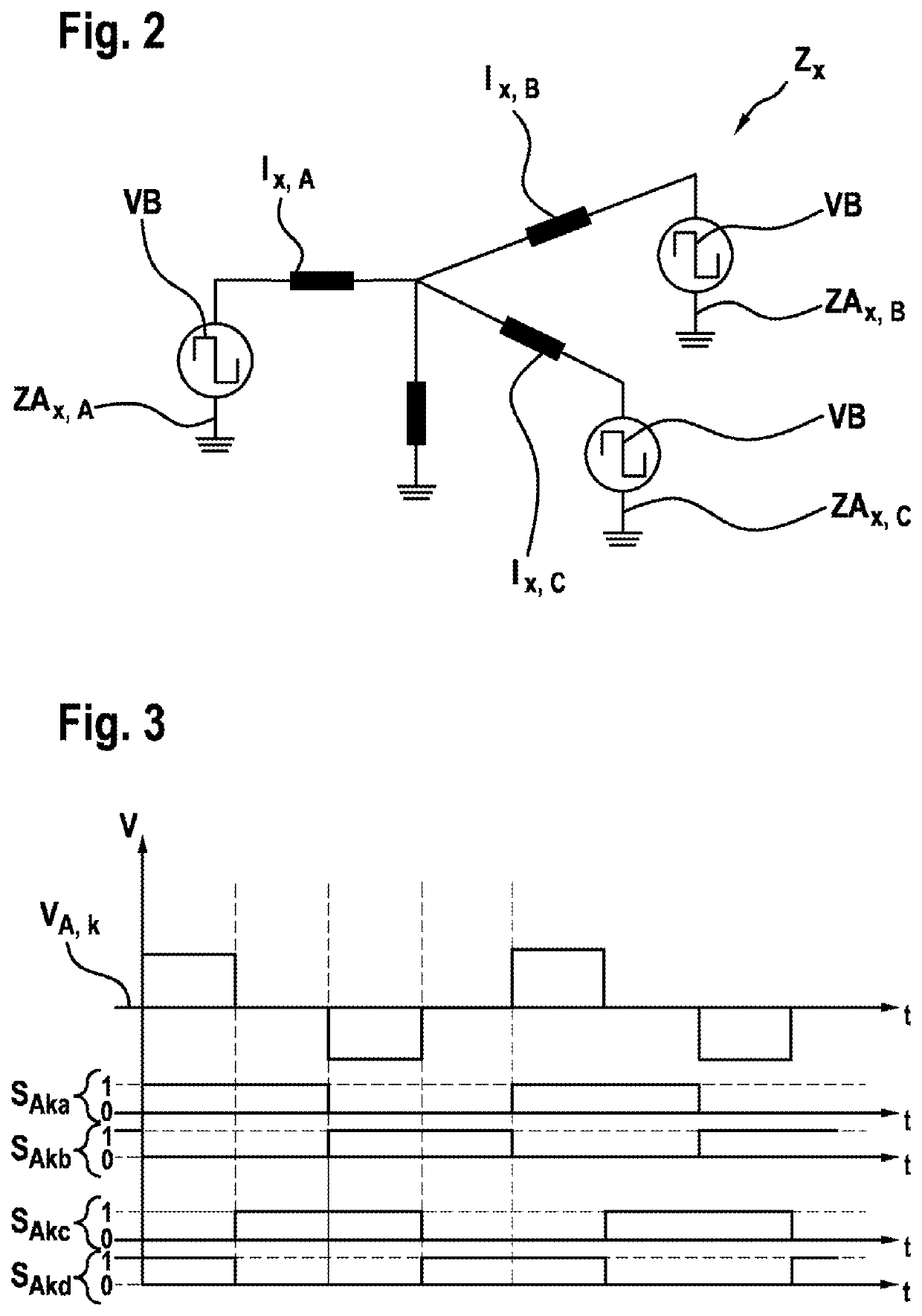
[0045]Each cell consists of three full-bridges VB and a transformer T having three windings—Wx,A, Wx,B, Wx,C or transformer coils and three cell terminals ZAx,A, ZAx,B and ZAx,C. In this case, the first index “x” stands for the number of the respective converter cell and the second index “A, B, C” stands for the individual term...


PUM


Abstract

The invention relates to a converter (K) for controlling power flows between at least three power networks (QAC, QHV, QNV) having different operating voltages (UA, UB, UC). The converter comprises at least three terminals (A, B, C), each of which is configured for electrically contacting one of the three power networks (QNV, QHV, QAC), and at least two converter cells (Z1, Z2), each having a transformer (T) having at least three transformer coils (W1,A, W1,B, W1,C, W2,A, W2,B, W2,C). At least one of the terminals (A, B, C) is connected to a series connection of converter cells (Z1, Z2), whereas at least one of the other terminals (A, B, C) is connected to parallel connection of converter cells (Z1, Z2) via a bidirectional serial line.

Description

BACKGROUND OF THE INVENTION[0001]The converter described here is able to be used, in particular, in the field of power electronics. Said converter is, in particular, a converter that makes possible omnidirectional power flows between three DC-isolated DC voltage sources. In this context, the term “omnidirectional” means that a power flow between the various DC sources in any direction and in a wide power range can be controlled by means of the converter.[0002]In modern electric as well as hybrid vehicles, two different on-board power supply systems are usually used: on the one hand, there is a low-voltage system (LV system), which is buffer-stored by way of a storage battery and supplies power to all low-voltage consumers such as on-board computers, lighting units and entertainment electronics. On the other hand, there is a high-voltage system (HV system), which is fed by way of a high-voltage storage battery and provides energy both for the drive and for the low-voltage system.[000...

Claims


Application Information

Patent Timeline
Patent Type & Authority Applications(United States)
IPC IPC(8): H02M3/28H02M3/335H02M7/217
CPCH02M3/285H02M3/33561H02M2001/0074H02M3/33584H02M2001/0077H02M7/217H02M2001/008H02M1/0064H02M1/0074H02M1/0077H02M1/008
Inventor BORTIS, DOMINIKSCHAEFER, JANNIK ROBINKOLAR, JOHANN W.
Owner ROBERT BOSCH GMBH
Why Eureka
Try Eureka