Hydrokinetic turbine system

a turbine system and hydrokinetic technology, applied in the field of turbine systems, can solve the problems of large-diameter rotors not making optimal use of the velocity distribution channel, affecting the efficiency of the system, and affecting the performance of the system, so as to achieve the effect of reducing the lift and drag force of the blades and the torque at the shaft, and without sacrificing performan

Pending Publication Date: 2020-03-19
EMRGY INC
View PDF16 Cites 4 Cited by
  • Summary
  • Abstract
  • Description
  • Claims
  • Application Information

AI Technical Summary

Benefits of technology

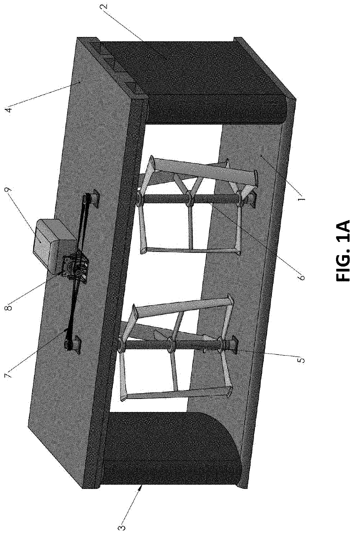
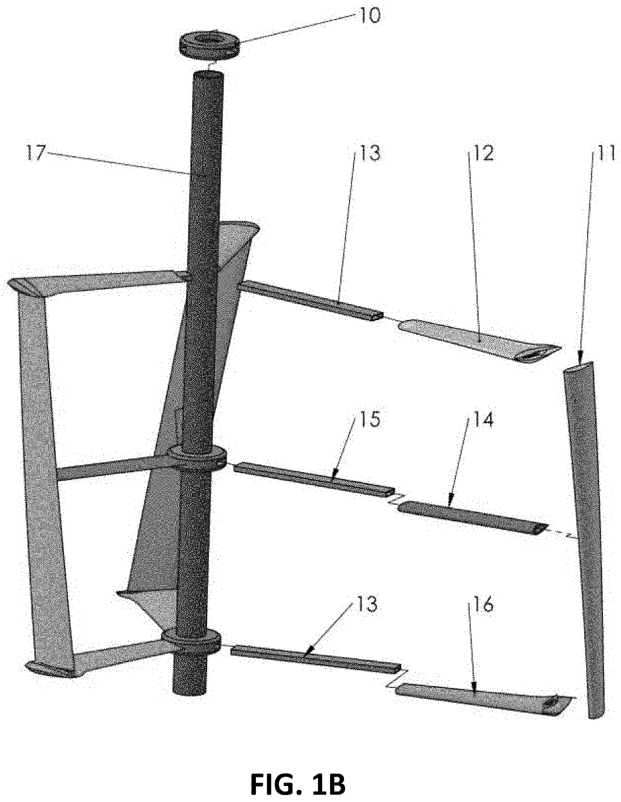
[0011]Generally, vertical-rotor hydrokinetic turbines perform best if the rotor's solidity, i.e. the portion of the circumference that is occupied by the blades of the turbine, is approx. 30%. Such a rotor operates (i.e. at the peak of the power curve) at a tip-speed ratio (TSR) of TSR≈2, which means that the speed of the blade is approximately twice the speed of the ambient water. Disclosed and described herein is a turbine system with one or more vertical rotors that each feature a very low solidity (approximately 11%), and the rotor operates at TSR≈3 without sacrificing performance. This has the advantage that the disclosed rotors spin faster than conventional vertical axis rotors, which reduces further the lift and drag forces on the blades and the torque at the shaft, and hence creates less wear and tear on the system.
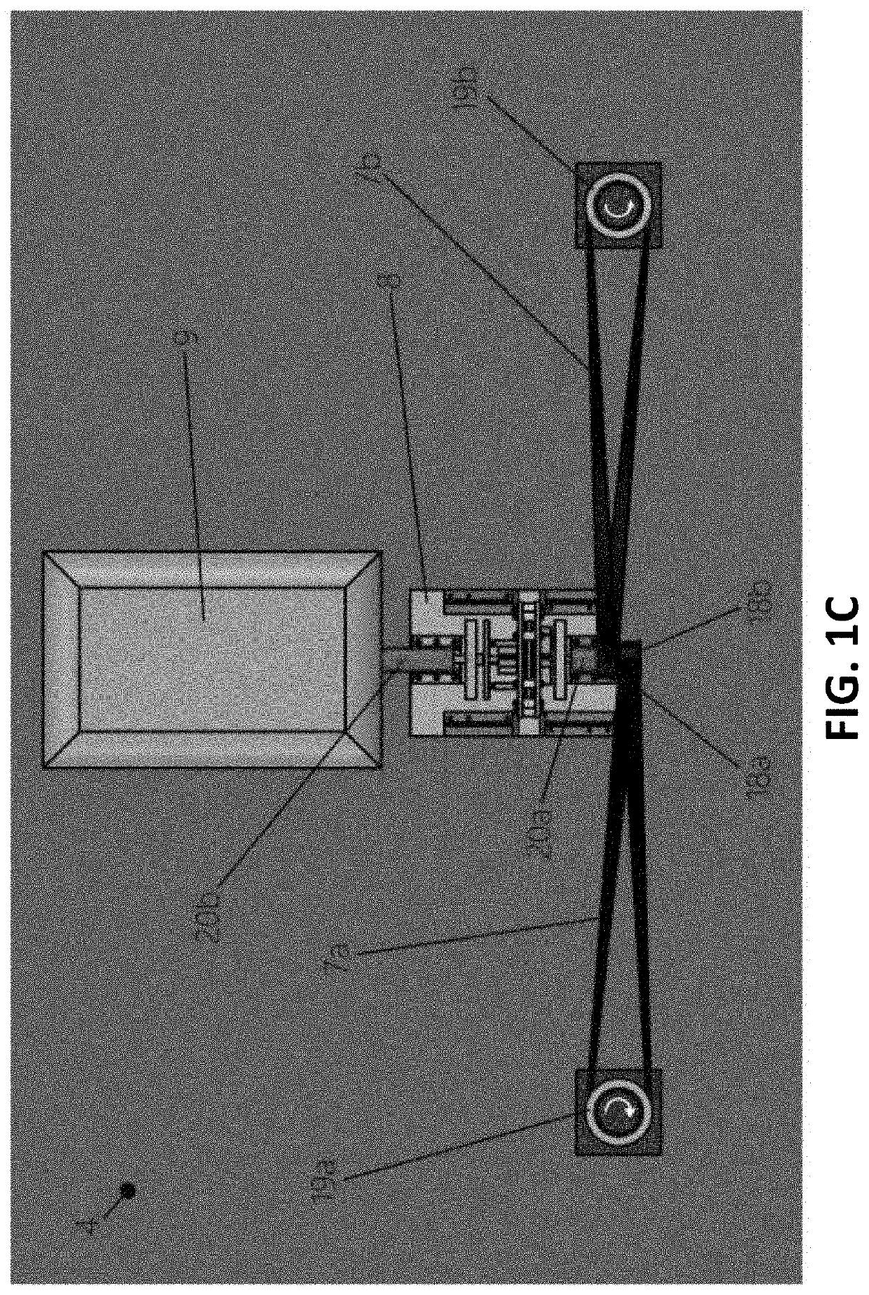
[0012]The disclosed rotors require smaller shafts, bearings and other structural components than a conventional high-solidity rotor and improved performance can be realized through use of a cycloidal magnetic gear system.

Problems solved by technology

If more than 66% of the cross-section is used, the flow is chocked and the performance will deteriorate.
The large-diameter rotor would not make optimum use of the channel's velocity distribution.
A wide rotor creates significant asymmetry of the flow in the channel and the upstroke and downstroke portion of the rotation are subjected to lower velocities and hence power generation is not at its maximum.
A larger gear ratio means greater losses in the gear.
However, mechanical, interlocking gears can wear and / or deteriorate over time, and often require extensive and regular maintenance to function and / or operate as intended.
The maintenance can be costly to both perform and also often requires the turbine system to be shut down, and be inoperable for an extended period of time.
Additionally, when the mechanical, interlocking gears wear, fail, break or become inoperable, the gear system and overall turbine system is rendered inoperable until the mechanical gears are fixed or replaced.

Method used


Image

  • Hydrokinetic turbine system
  • Hydrokinetic turbine system
  • Hydrokinetic turbine system

Examples


Embodiment Construction

[0028]Reference will now be made in detail to representative embodiments illustrated in the accompanying drawings. It should be understood that the following descriptions are not intended to limit the embodiments to one preferred embodiment. To the contrary, it is intended to cover alternatives, modifications, and equivalents as can be included within the spirit and scope of the described embodiments as defined by the appended claims.

[0029]As used in the specification and the appended claims, the singular forms “a,”“an” and “the” include plural referents unless the context clearly dictates otherwise. Ranges may be expressed herein as from “about” one particular value, and / or to “about” another particular value. When such a range is expressed, another embodiment includes from the one particular value and / or to the other particular value. Similarly, when values are expressed as approximations, by use of the antecedent “about,” it will be understood that the particular value forms anot...


PUM


Abstract

Hydrokinetic fluid turbines utilize a flowing body of liquid to translate the kinetic energy of the fluid into electric power or other useful energy. The available kinetic energy is proportional to the squared fluid velocity in an open channel with a fixed cross-sectional area. The proposed twin turbine system coupled with a cycloidal magnetic gear exploits the hydrokinetic energy existing in open-channels.

Description

CROSS REFERENCE TO RELATED APPLICATIONS[0001]This application is a national stage entry of, and claims the benefit of and priority to International Patent App. No. PCT / US2017 / 024511, filed on Mar. 28, 2017, and entitled “TURBINE HYDROKINETIC ENERGY SYSTEM UTILIZING CYCLOIDAL MAGNETIC GEARS”, and claims benefit under 35 U.S.C. § 119 of U.S. Provisional Patent Application No. 62 / 313,856, filed Mar. 28, 2016, and entitled “TWIN-TURBINE HYDROKINETIC ENERGY SYSTEM,” all of which are incorporated herein by reference as if set forth herein in their entireties.GOVERNMENT LICENSE RIGHTS[0002]This invention was made with government support under Award Number DE-EE0007249 awarded by the United States Department of Energy (DoE). The government has certain rights in the invention.TECHNICAL FIELD[0003]The disclosure relates generally to turbine systems, more particularly to hydrokinetic fluid turbines for open channels. More specifically, the disclosure relates to a twin-turbine hydrokinetic flui...

Claims


Application Information

Patent Timeline
Patent Type & Authority Applications(United States)
IPC IPC(8): F03B17/06H02K7/18H02K7/10H02K49/10
CPCF03B17/065H02K49/102H02K7/1823H02K7/1004H02K51/00H02K7/116F03B17/063F05B2240/133F05B2250/72F05B2260/404Y02E10/30Y02E10/20
Inventor STOESSER, THORSTENMORRIS, TONYMORRIS, EMILY A.WALSH, ANTHONYVANSELOUS, JOSEPH S.PARYS, CHESTER LOUISTUTAS, BRIAN DAVID
Owner EMRGY INC
Why Eureka
Try Eureka