3D block modelling of a resource boundary in a post-blast muckpile to optimize destination delineation

a resource boundary and 3d block technology, applied in geomodelling, geophysical research, instruments, etc., can solve the problems of not being mathematically optimized in situ for value, ore loss, and not taking into account the three-dimensional post-blast shape of resources, so as to improve the efficiency of mining operations.

Active Publication Date: 2020-03-19
ORICA USA
View PDF31 Cites 12 Cited by
  • Summary
  • Abstract
  • Description
  • Claims
  • Application Information

AI Technical Summary

Benefits of technology

[0010]It is therefore an object to provide a method for determining a post-blast shape of a resourc

Problems solved by technology

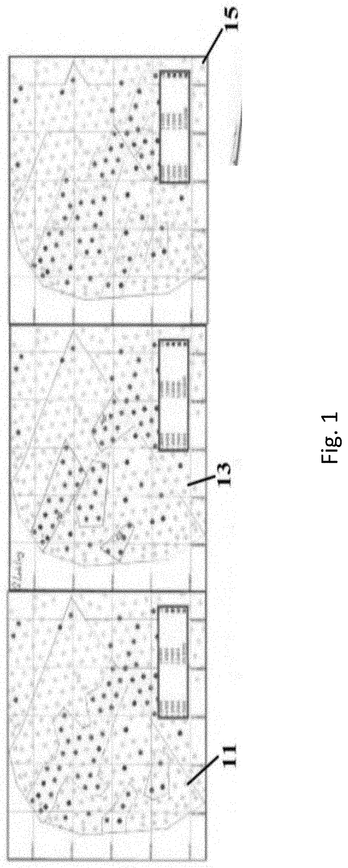
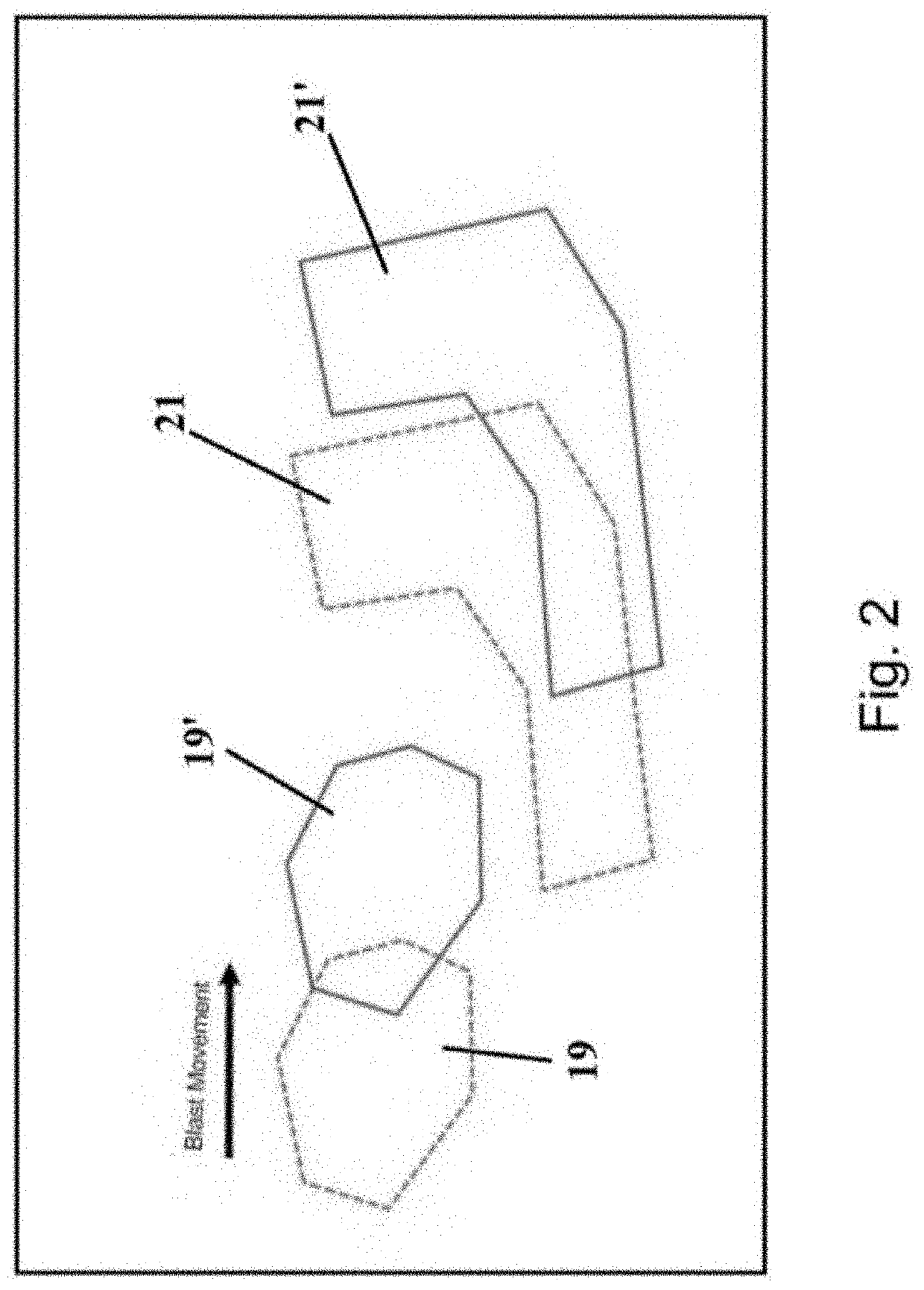
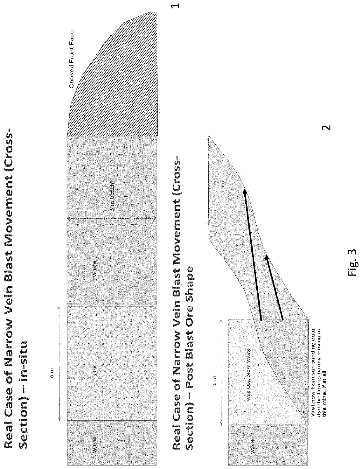
However, the movement of the rock caused by blasting has an unfavorable effect on the separation of the ore and waste region in the muck pile, causing either ore loss (the ore is wrongly categorized as waste and sent to the waste dump) and/or ore dilution (waste

Method used


Image

  • 3D block modelling of a resource boundary in a post-blast muckpile to optimize destination delineation
  • 3D block modelling of a resource boundary in a post-blast muckpile to optimize destination delineation
  • 3D block modelling of a resource boundary in a post-blast muckpile to optimize destination delineation

Examples


Embodiment Construction

[0025]Although any methods and materials similar or equivalent to those described herein, can be used in the practice or testing of the present method, the preferred methods and materials are now described. Reference will now be made in detail, to the presently preferred embodiments of the method, including the examples of which are illustrated in the accompanying drawings. In the drawings, like numerals will be used in order to represent like features of the present method.

[0026]Unless specifically defined otherwise, all scientific and technical terms, used herein, have the same ordinary meaning as would be commonly understood by one of ordinary skill in the art to which this method belongs.

[0027]Referring now to FIG. 6, the 3-D block modelling method of a resource boundary in a post-blast muckpile to optimize desired delineation, for example, grade control polygons, is provided. An in-situ pre-blast model of a resource deposit in a blast volume to be mined, blast design informatio...


PUM


Abstract

A method for 3-D block modelling of a resource boundary in a post-blast muckpile to optimize destination delineation for resource control is provided. An in-situ pre-blast model of an ore deposit to be mined, movement data, blast design and explosive loading information, and post-blast topographic data are input in to the memory of a general purpose computer. Using the pre-blast block model, movement data, blast design and explosive loading information, and post-blast topographic data a three-dimensional vector field is generated. The method uses the three-dimensional vector field to move a plurality of centroids of the in-situ block model to populate a three-dimensional post-blast location. Then method optimizes the populated three dimensional post-blast location to determine a plurality of sets of optimal dig boundaries.

Description

[0001]This application claims the benefit of U.S. Provisional Application No. 62 / 648,291 filed Mar. 26, 2018 for 3D BLOCK MODELLING OF AN ORE BOUNDARY IN A POST-BLAST MUCKPILE TO OPTIMIZE DIG LINES and is incorporated by reference herein.BACKGROUND[0002]The present method relates to optimization of destination delineation in a post blast muckpile. In particular, it relates to a 3D modeling of post-blast ore grade boundaries to optimize the location of grade control polygons.[0003]The surface mining industry is primarily comprised of industrial minerals (aggregates, cement, etc), coal, and precious and base metals. This business serves the precious and base metals markets which produce minerals, including, but not limited to, copper, iron, PGMs, gold, silver, zinc, nickel, and rare earth elements.[0004]In open pit mines, a bench blasting method is often used to allow the removal of a determined volume of a given rock mass. These mine deposits are highly heterogeneous with the resourc...

Claims


Application Information

Patent Timeline
IPC IPC(8): G06F17/50G01V99/00
CPCG01C11/04G06F30/20G01C15/002G01S19/14G01V99/005G01S17/42G01S17/88
Inventor HUNT, TIMOTHY WILLIAMLA ROSA, DAVID MARIOSEAMAN, JEFFREY SCOTT
Owner ORICA USA
Why Eureka
Try Eureka