
Twist drill

a drill bit and twisting technology, applied in the direction of twisting drill bit, drilling tool, manufacturing tool, etc., can solve the problems of large constrained drilling efficiency, low speed and efficiency, and difficulty in positioning the drill bit, so as to improve drilling efficiency, reduce the reaction force of each cutting blade, and improve drilling efficiency

Active Publication Date: 2020-03-26
WANG HONGJIA
View PDF0 Cites 2 Cited by
  • Summary
  • Abstract
  • Description
  • Claims
  • Application Information

AI Technical Summary

Benefits of technology

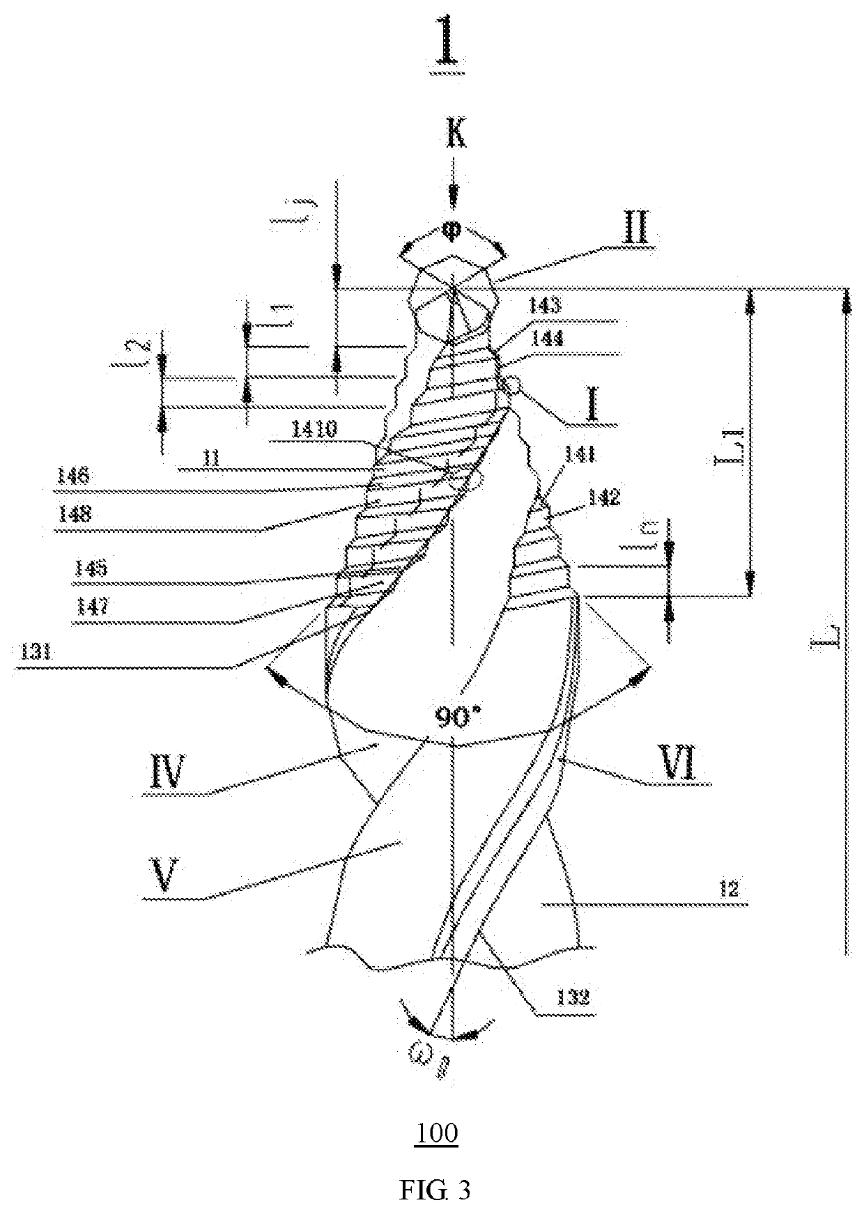
The present invention is a twist drill with a cone portion at the front end that has a spiral flute for cutting chips, and a sequential increase in diameter of cutting blade groups. This design allows for reasonably distributed cutting force, reduces burrs, and improves drilling efficiency. The drill also includes a top blade on the tip for positioning. Compared to existing drills with symmetrical main blades, the present invention has a higher drilling efficiency and reduces the reaction force on the cutting blades, preventing them from damage. The technical effect of this design is smoother and more efficient drilling without compromising power.

Problems solved by technology

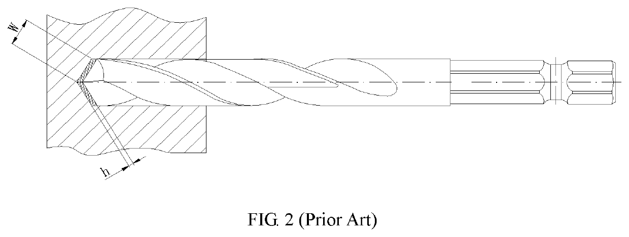
Twist drills are commonly used in the places away from other metal cutting machines such as drill presses, and when a hand-held electric tool is used for the drilling operation, the drilling efficiency is greatly constrained due to limitations of arm strength of a worker, power of the electric tool and the like.
Thus, the existing twist drill is difficult to position the drill hole, and low in speed and efficiency.
Meanwhile, relatively large reaction forces are also applied onto two cutting edges, so the cutting edges are easy to be damaged.

Method used


Image

  • Twist drill
  • Twist drill
  • Twist drill

Examples


Embodiment Construction

[0039]The technical solutions in the embodiments of the present invention are clearly and completely described in the following with reference to the accompanying drawings. It is obvious that the described embodiments are only a part of the embodiments of the present invention. Any other embodiments obtained by the skilled in the art based on the embodiments of the present invention without departing from the inventive scope shall fall within the scope of the present invention.

[0040]It should be noted that terms such as “up”, “down”, “left”, “right”, “front”, “rear” in the embodiments of the present invention are only used to explain the relative position and movement, etc. of components.

[0041]In addition, terms “first”, “second”, and the like in the present invention are used for description only, and are not intended to indicate or imply their relative importance or the number of technical features, which explicitly or implicitly indicates that one or more features defined by “fir...


PUM


Abstract

The present invention provides a twist drill. A cone portion is provided at a front end of the operating portion, and an exterior surface of the operating portion is provided with a spiral flute for shunting cutting chips. The exterior surface of the cone portion is provided with a plurality of composite cutting blade groups which are sequentially enlarged in diameter from the front end to the rear end of the cone portion. The cone portion is provided with a top blade on the tip. In use, the top blade is used for positioning, and the cutting process is carried out by the top blade and the composite cutting blade groups.

Description

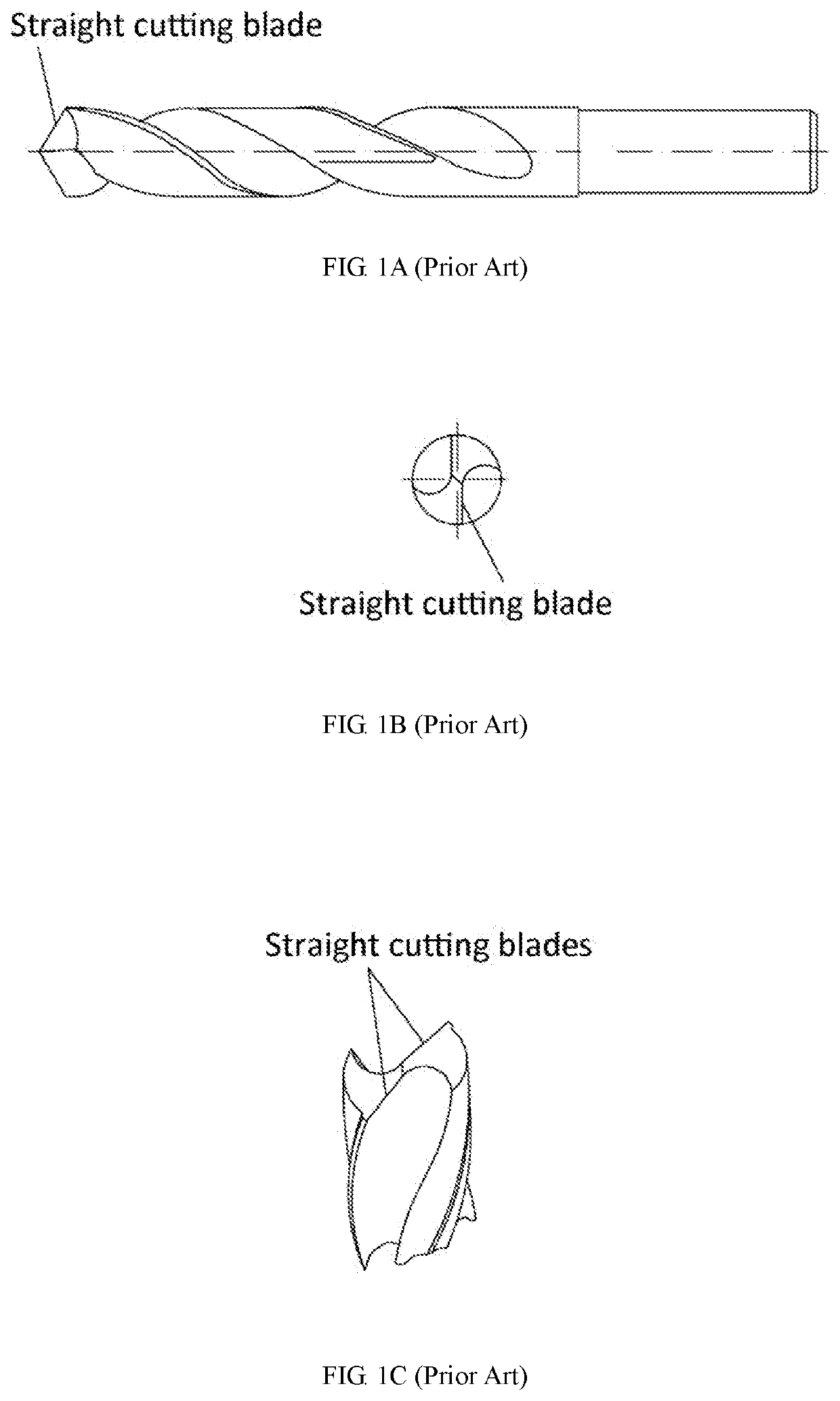
CROSS-REFERENCE TO RELATED APPLICATIONS[0001]This application is a continuation-in-part of U.S. patent application Ser. No. 15 / 847,900 filed on Dec. 19, 2017, which is a continuation of International Patent Application No. PCT / CN2016 / 073767 filed on Feb. 14, 2016. The contents of the aforementioned application, including any intervening amendments thereto, are incorporated herein by reference in its entirety.TECHNICAL FIELD[0002]The application relates to metal cutting and metal cutting tools, more particularly, to a twist drill.BACKGROUND OF THE INVENTION[0003]FIGS. 1A-B are schematic diagrams of a conventional twist drill. FIG. 1A is a front view of the twist drill; FIG. 1B is a top view of a drill tip; and FIG. 1C is a perspective view of a truncate twist drill. Twist drills are commonly used in the places away from other metal cutting machines such as drill presses, and when a hand-held electric tool is used for the drilling operation, the drilling efficiency is greatly constrai...

Claims


Application Information

Patent Timeline
IPC IPC(8): B23B51/02
CPCB23B2251/24B23B51/02B23B51/009B23B51/0081B23B2251/04
Inventor WANG, HONGJIA
Owner WANG HONGJIA
Learn More