Regulating device for an electric machine, electric drive system, and method for regulating an electric machine

a technology of electric drive system and electric machine, which is applied in the direction of control system, motor control for motor oscillation damping, electrical apparatus, etc., can solve the problems of irregular torques containing harmonics, inability to achieve ideal sinusoidal flux distribution in air gap, and inability to control the electric machine precisely and efficiently. , to achieve the effect of reducing running properties, cost-effectiveness, and precise and efficient regulation

Inactive Publication Date: 2020-03-26
ROBERT BOSCH GMBH
View PDF3 Cites 0 Cited by
  • Summary
  • Abstract
  • Description
  • Claims
  • Application Information

AI Technical Summary

Benefits of technology

[0013]As a result of such decoupling of the interference variable compensation and the regulation of the target value, it is possible to achieve a particularly precise and efficient regulation for an electric machine. An existing regulation system without interference compensation can be incorporated unchanged.
[0014]Such an improved regulation of the electric machine with interference variable compensation thus enables the use of modern, cost-effectively optimized electric machines, which without interference variable compensation could only provide diminished running properties. With the regulating device according to the invention, the running properties of the electric machines can thus be improved. In particular, the price for an electric drive system can also be reduced by the use of modern cost-effective electric machines.
[0015]According to an embodiment, the operating point of the electric machine comprises a torque, a magnetic flux of the electric machine and / or an electric current of the electric machine. In particular, the operating point can comprise for example the phase current or the phase currents in the electrical phases of the machine. The operating point of the electric machine can be both a directly detectable or detected operating point, or alternatively also an operating point which is calculated beforehand, possibly indirectly, from other variables of the electric machine. Thus, conclusions can also be drawn about the torque in the electric machine, for example from known electric currents in the machine, without the torque having to be detected directly by means of a sensor. In the case of a regulating device which for example uses the torque of an electric machine as an operating point, the torque ripple can thus be reduced. This enables particularly smooth running of the machine.
[0016]According to an embodiment, the interference variable at the operating point comprises a ripple or a harmonic oscillation, for example in a torque. Ripples or harmonic oscillations are a widespread phenomenon in electric drive systems. The smooth running of the electric machine can be increased by minimizing such interference variables.

Problems solved by technology

On account of their design, induction machines, such as for example cage rotor asynchronous machines or permanent magnet synchronous machines, do not have an ideal sinusoidal flux distribution in the air gap.
During operation, this leads to irregular torques containing harmonics during regulation with sinusoidal currents.

Method used


Image

  • Regulating device for an electric machine, electric drive system, and method for regulating an electric machine

Examples


Embodiment Construction

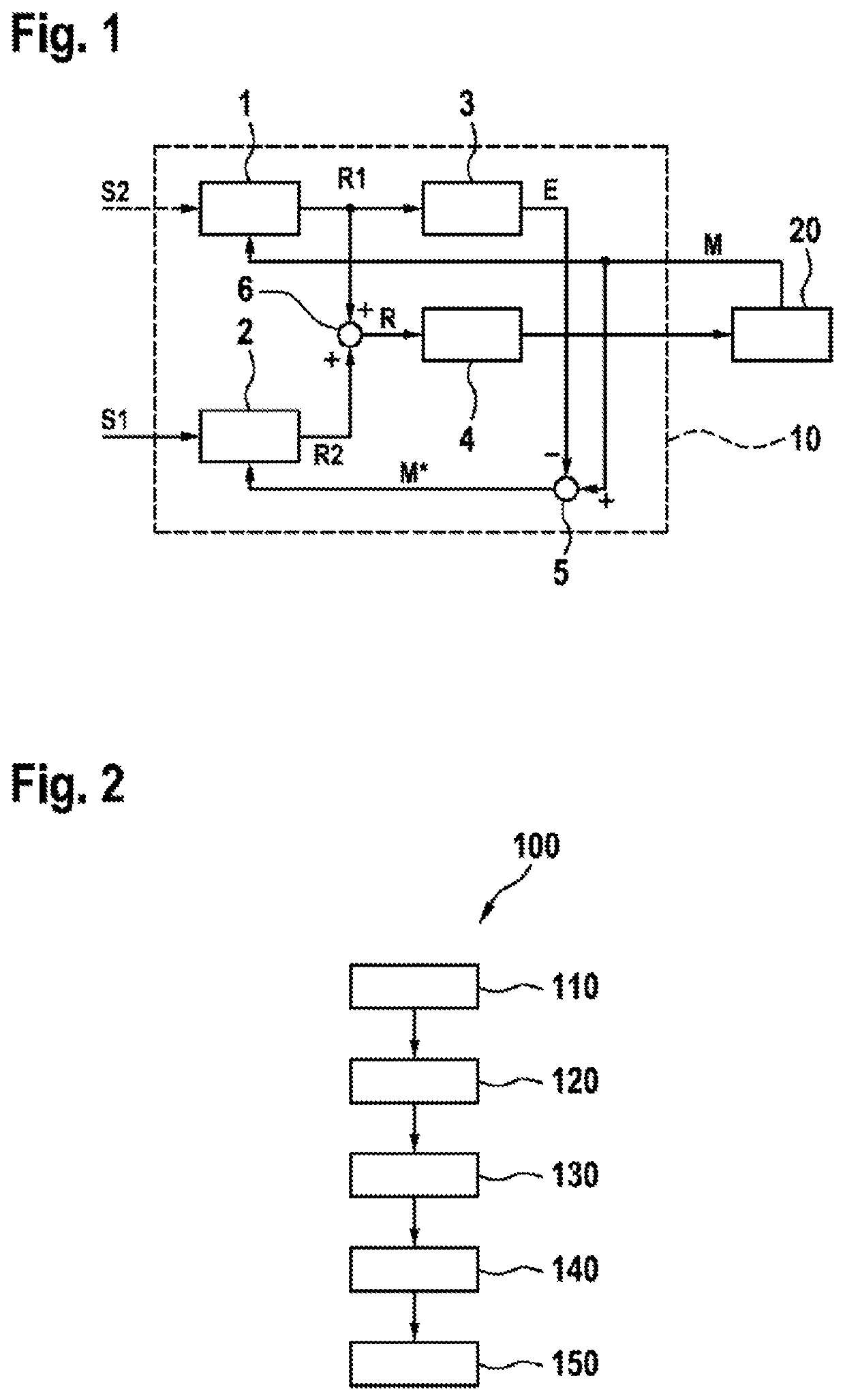
[0027]FIG. 1 shows a schematic representation of an electric drive system with a regulating device for an electric machine 20. The electric drive system comprises a regulating device 10 in electric machine 20. Regulating device 10 comprises a first regulating unit 1, a second regulating unit 2, a computing device 3 and a control device 4. A first target variable R1, to which an operating point of electric machine 20 is to be set, can for example be specified on second regulating unit 2. This first target value 51 can for example be a torque, which is to be set in electric machine 20. Moreover, any other operating point, such as for example an electric current to electric machine 20, and also any other operating points are however also possible. Second regulating unit 2 then determines, from specified target value 51 and a current value of the operating point, a target variable R2 for driving electric machine 20. In contrast with a conventional regulation, it is not the actual curren...


PUM


Abstract

The invention relates to the regulation of an electric machine, wherein an interference variable is compensated for and simultaneously a target value is set. In the process, two mutually independent control loops are provided. A first control loop is used to compensate for the interference variable, and a second control loop is used to set a specified target value. When the specified target value is being regulated, the control loop is decoupled from the interference variable compensation process. In this manner, a modular independent regulation can be achieved for the target value and the interference variable compensation process.

Description

BACKGROUND OF THE INVENTION[0001]The present invention relates to a regulating device for an electric machine, an electric drive system with such a regulating device and a method for regulating an electric machine. In particular, the present invention relates to the regulation of an electric machine for minimizing an interference variable.[0002]Publication DE 10 2009 000 930 A1 discloses a method and an arrangement for reducing the torque ripple in a permanent magnet motor system. The motor system comprises a permanent magnet motor, which is coupled to an inverter. The method described in this publication comprises a step for modifying operating control signals, in order to generate ripple-reducing operating control signals. These modified operating control signals are delivered to an inverter for controlling the permanent magnet motor.[0003]On account of their design, induction machines, such as for example cage rotor asynchronous machines or permanent magnet synchronous machines, ...

Claims


Application Information

Patent Timeline
Patent Type & Authority Applications(United States)
IPC IPC(8): H02P23/04
CPCH02P2207/05H02P2207/01H02P23/04H02P6/10H02P23/0022H02P29/50
Inventor MALCHOW, FLORIANMANDERLA, MAXIMILIAN
Owner ROBERT BOSCH GMBH
Why Eureka
Try Eureka