Light emitting device and lighting fixture provided with the same

a technology of light emitting devices and lighting fixtures, which is applied in the direction of luminescent compositions, semiconductor devices, chemistry apparatus and processes, etc., can solve the problems of eye fatigue, glare, eye fatigue, etc., and achieve excellent visual work and reduce eye fatigu

Active Publication Date: 2020-04-02
NICHIA CORP
View PDF0 Cites 0 Cited by
  • Summary
  • Abstract
  • Description
  • Claims
  • Application Information

AI Technical Summary

Benefits of technology

[0026]In accordance with the present disclosure, it is possible to provide a light emitting device capable of reducing the human eye fatigue and having light emission spectra with excellent visual work and a lighting fixture provided with the same.

Problems solved by technology

When the band width (wavelength width) centering on 555 nm in the light emission spectrum is narrow, the adjusting power of the eyes is lowered, leading to eye fatigue.
In addition, as for the human eye fatigue, glare is also feared in not only photopic vision but also mesopic vision.

Method used


Image

  • Light emitting device and lighting fixture provided with the same
  • Light emitting device and lighting fixture provided with the same
  • Light emitting device and lighting fixture provided with the same

Examples


example 1

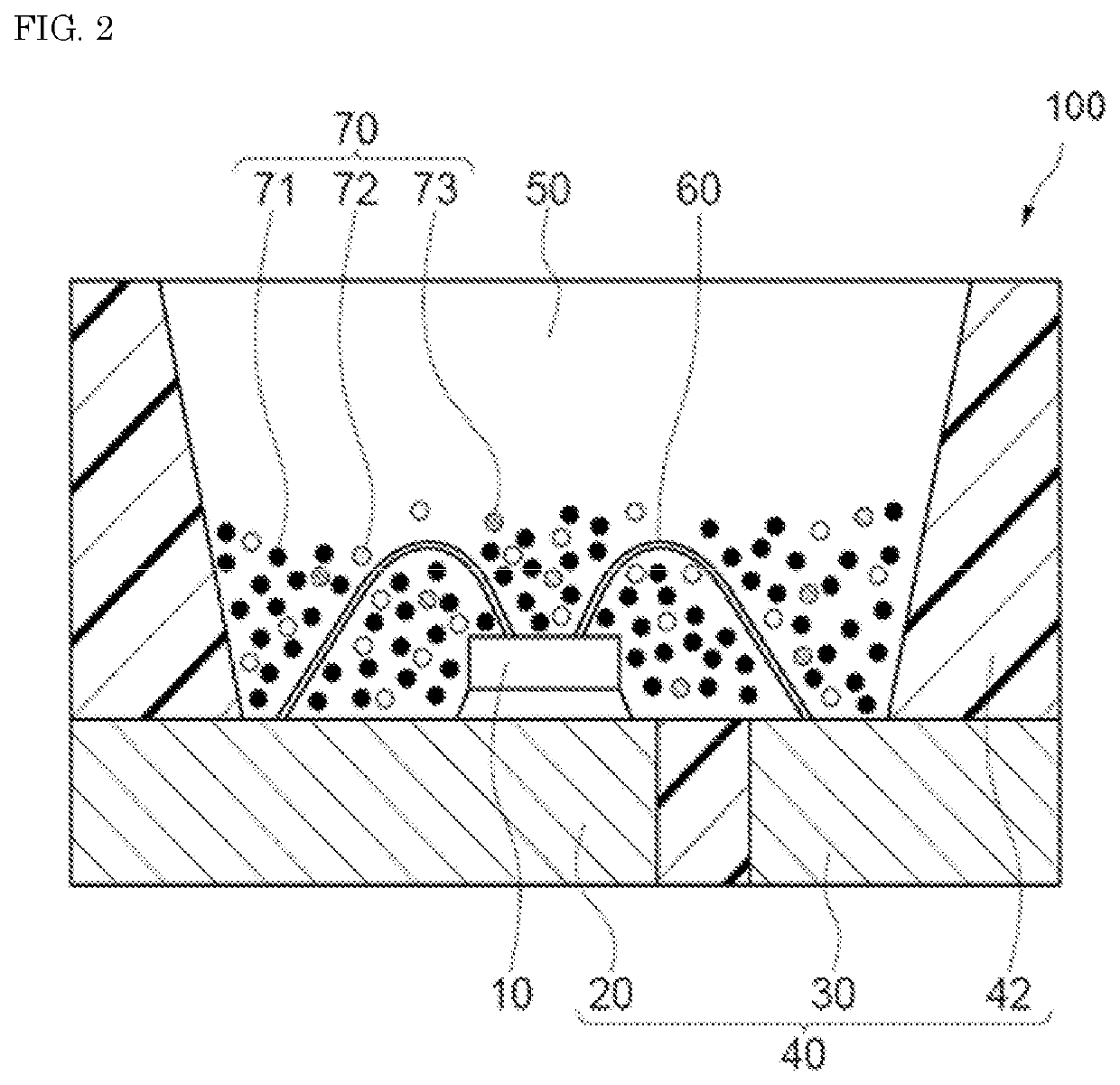
[0125]The fluorescent material 70 in which the first fluorescent material 71, the second fluorescent material 72, and the third fluorescent material 73 were blended such that the chromaticity coordinate in CIE1931 was located in the vicinity of X=0.312 and Y=0.328, and a silicone resin were mixed and dispersed, and the dispersion was then degassed to obtain a resin composition for fluorescent member. The fluorescent material total amount in the resin composition for fluorescent member was 68.6% by mass based on 100% by mass of the resin. In addition, the content MP1 of SAE that is the first fluorescent material 71 was 43.7% by mass, the content MP2 of LAG3 that is the second fluorescent material 72 was 45.8% by mass, and the content MP3 of SCASN1 that is the third fluorescent material 73 was 10.5% by mass relative to the fluorescent material total amount. Next, the molded article 40 having a convex as shown in FIG. 2 was prepared; the light emitting element 10 having a light emissio...

examples 2 to 5

, and 23, and Comparative Examples 1, 2 and 11

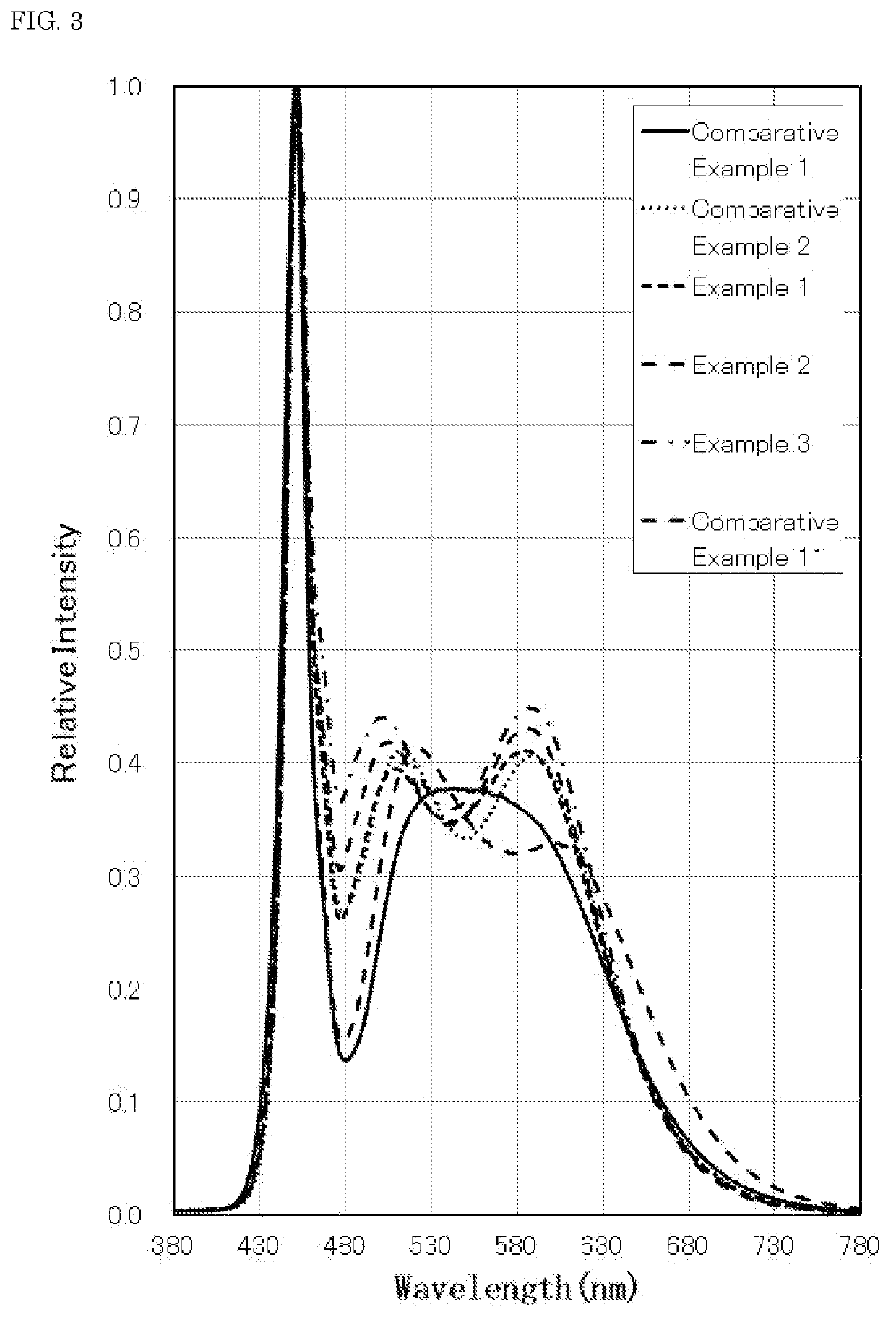
[0126]Light emitting devices were fabricated in the same manner as in Example 1, except for changing the kinds of the first fluorescent material 71, the second fluorescent material 72, and the third fluorescent material 73 and the content of each of the fluorescent materials relative to the fluorescent material total amount as shown in the following Table 3.

TABLE 3Fluorescent material content (% by mass)FirstSecondThirdContentFluorescent materialfluorescentfluorescentfluorescentrelative toFirstSecondmaterialmaterialmaterialresinfluorescentfluorescentThird fluorescentMP1MP2MP3(% by mass)materialmaterialmaterialComparative14.583.22.348.2SAEYAG1 / LAG3SCASN3 / SCASN4Example 1(70 / 30)(50 / 50)Comparative71.818.49.969.7SAEYAG1SCASN1Example 2Example 143.745.810.568.6SAELAG3SCASN1Example 237.253.29.580.6SAELAG5SCASN1Example 336.154.29.783.1SAEGLAG6SCASN1Example 424.366.19.682.3SAEGLAG6SCASN1Example 513.177.39.676.3SAEGLAG6SCASN1Example 2324.073.82.383...

examples 6 to 10

, and 24, and Comparative Examples 3, 4 and 12

[0127]Light emitting devices were fabricated in the same manner as in Example 1, except for blending the first fluorescent material 71, the second fluorescent material 72, and the third fluorescent material 73 such that the chromaticity coordinate in CIE1931 was located in the vicinity of X=0.345 and Y=0.355; and changing the kinds of the first fluorescent material 71, the second fluorescent material 72, and the third fluorescent material 73 and the content of each of the fluorescent materials relative to the fluorescent material total amount as shown in the following Table 4. The aforementioned chromaticity coordinate is about 5,000K in terms of the correlated color temperature of the light emitting device and is corresponding to a range where the correlated color temperature is 4,500K or higher and lower than 5,700K.

TABLE 4Fluorescent material content (% by mass)FirstSecondThirdContentFluorescent materialfluorescentfluorescentfluoresce...


PUM

PropertyMeasurementUnit
light emission peak wavelengthaaaaaaaaaa

Abstract

Provided is a light emitting device, comprising: a light emitting element including a light emission peak wavelength in a range of 440 nm or more and 470 nm or less; a first fluorescent material having a light emission peak wavelength in a range of 480 nm or more and 518 nm or less; a second fluorescent material having a light emission peak wavelength in a range of 510 nm or more and less than 590 nm and having an x value of the chromaticity coordinate in CIE1931 in a range of 0.27 or more and 0.40 or less; and a third fluorescent material having a light emission peak wavelength in a range of 590 nm or more and 670 nm or less. The light emitting device is capable of reducing the human eye fatigue and having a light emission spectrum with excellent visual work.

Description

CROSS-REFERENCE TO RELATED PATENT APPLICATION[0001]This application claims priority to Japanese Patent Application No. 2018-184537, filed on Sep. 28, 2018, and Japanese Patent Application No. 2019-170972, filed on Sep. 20, 2019, the entire disclosures of which are incorporated herein by references in their entirety.BACKGROUNDTechnical Field[0002]The present disclosure relates to a light emitting device and a lighting fixture provided with the same.Description of Related Art[0003]As a light emitting device using a light emitting element, such as a light emitting diode (hereinafter referred to as “LED”), a white light emitting device using a light emitting element of blue light emission and a fluorescent material of yellow light emission is well known. Such a light emitting device is used in a broad field inclusive of general lighting, in-vehicle lighting, display, and backlight for liquid crystal. With the spread of LED lighting, lighting focusing on any influences of blue light cont...

Claims


Application Information

Patent Timeline
Patent Type & Authority Applications(United States)
IPC IPC(8): H01L33/50
CPCH01L33/504H01L33/507H01L33/486H01L33/62C09K11/77348C09K11/7774C09K11/77347C09K11/7734C09K11/7707C09K11/0883H01L33/502
Inventor FUJIO, KAZUSHIGEWAKUI, SADAKAZU
Owner NICHIA CORP
Why Eureka
Try Eureka