Orthogonally Delivered Transcatheter Heart Valve Frame for Valve in Valve Prosthesis

a prosthetic valve and transcatheter technology, applied in the field of orthogonally delivered transcatheter prosthetic valve frame for valve in valve prosthesis, can solve the problems of prone to fracture of the strut of the valve, not fully correcting the valve problem, and placing the heart valve in the descending aorta instead of the heart itsel

Active Publication Date: 2020-04-23
VDYNE INC
View PDF0 Cites 21 Cited by
  • Summary
  • Abstract
  • Description
  • Claims
  • Application Information

AI Technical Summary

Benefits of technology

[0098]FIG. 64 is an illustration of a low-profile, e.g. 8-20 mm, side-loaded valve frame shown housed within the delivery catheter.
[0099]FIG. 65 is an illustration of a low-profile, e.g. 8-20 mm, side-loaded valve frame shown partially housed within a delivery catheter and partially laterally ejected from the delivery catheter and positioned for deployment against the anterior side of the native annulus.
[0100]FIG. 66 is an illustration of a low-profile, e.g. 8-20 mm, side-loaded valve frame shown ejected from the delivery catheter and positioned against the anterior side of the native annulus.
[0101]FIG. 67 is an illustration of a side or plan view of a low-profile, e.g. 8-20 mm, side-loaded valve frame shown deployed into the native annulus of a heart valve.

Problems solved by technology

However, one downside of this design was that it could only be placed in the descending aorta instead of the heart itself.
For this reason it did not fully correct the valve problem, only alleviate the symptoms.
However, the struts of these valves tended to fracture from fatigue over time.
However, a downside of this design is that it allows some regurgitation.
Additionally, a problem with stent-style replacement valves is that they often continue to have the regurgitation or leakage problems of prior generations of valves, as well as require expensive materials engineering in order to cope with the 100's of millions of cycles encountered during just a few years of normal heart function.

Method used


Image

  • Orthogonally Delivered Transcatheter Heart Valve Frame for Valve in Valve Prosthesis
  • Orthogonally Delivered Transcatheter Heart Valve Frame for Valve in Valve Prosthesis
  • Orthogonally Delivered Transcatheter Heart Valve Frame for Valve in Valve Prosthesis

Examples


example

[0184]The transcatheter prosthetic heart valve may be percutaneously delivered using a transcatheter process via the femoral through the inferior vena cava (IVC), superior vena cava (SVC), jugular vein, brachial vein, sub-xyphoid, intercostal access across the chest wall, and trans-septal through the fossa ovalis.

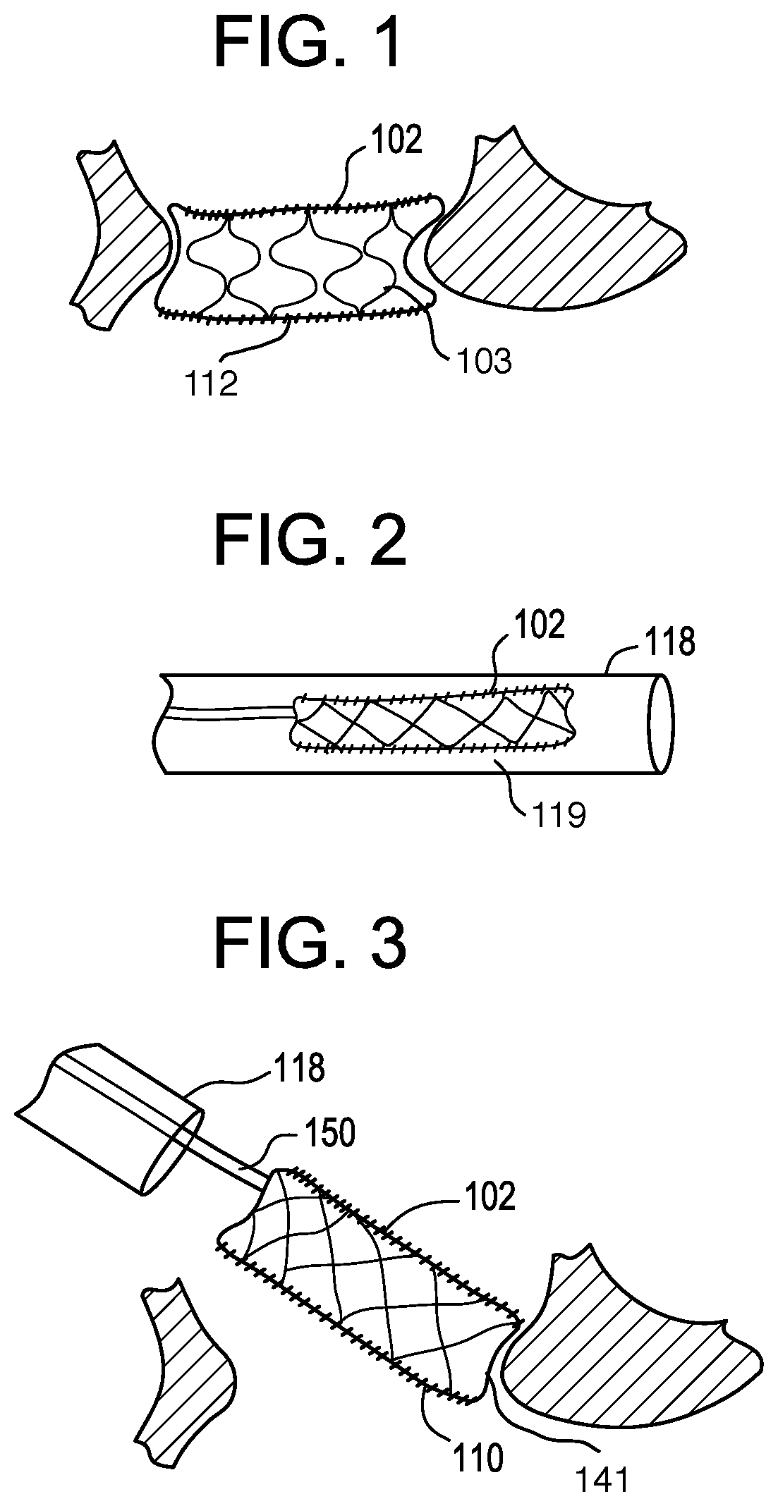
[0185]The device is delivered via catheter to the right or left atrium and is expanded from a compressed shape that fits with the internal diameter of the catheter lumen. The compressed valve is loaded external to the patient into the delivery catheter, and is then pushed out of the catheter when the capsule arrives to the atrium. The cardiac treatment technician visualizes this delivery using available imaging techniques such as fluoroscopy or ultrasound, and in a preferred embodiment the valve frame self-expands upon release from the catheter since it is constructed in part from shape-memory material, such as Nitinol®, a nickel-titanium alloy used in biomedical implants.

[...


PUM


Abstract

The invention relates to a transcatheter heart valve replacement (A62F2/2412), and in particular an orthogonally delivered transcatheter prosthetic valve frame having a tubular frame for mounting a flow control component wherein the valve frame is compressible to a compressed configuration for sideways or lateral introduction into the body using a delivery catheter for implanting at a desired location in the body, where the compressed configuration has a long-axis oriented roughly perpendicular to the central axis of the native annulus, wherein the long-axis of the compressed configuration of the valve is substantially parallel to a length-wise cylindrical axis of the delivery catheter, and wherein the valve has a height of about 5-60 mm and a diameter of about 25-80 mm.

Description

CROSS-REFERENCE TO RELATED APPLICATIONS[0001]Provided by Application Data Sheet per USPTO rules.STATEMENT REGARDING FEDERALLY SPONSORED R&D[0002]Provided by Application Data Sheet per with USPTO rules.NAMES OF PARTIES TO JOINT RESEARCH AGREEMENT[0003]Provided by Application Data Sheet per with USPTO rules.REFERENCE TO SEQUENCE LISTING[0004]Provided by Application Data Sheet per USPTO rules.STATEMENT RE PRIOR DISCLOSURES[0005]Provided by Application Data Sheet per USPTO rules.BACKGROUND OF THE INVENTIONField of the Invention[0006]The invention relates to an Orthogonally Delivered Transcatheter Heart Valve Frame for Valve in Valve Prosthesis (A62F2 / 2412).Description of the Related Art[0007]In 1952 surgeons implanted the first mechanical heart valve. This first valve was a ball valve and it was designed by Dr. Charles Hufnagel. The recipient of this valve was a 30-year-old woman who could lead a normal life after the surgery. However, one downside of this design was that it could only ...

Claims


Application Information

Patent Timeline
Patent Type & Authority Applications(United States)
IPC IPC(8): A61F2/24
CPCA61F2/2469A61F2/2418A61F2/243A61F2/2439A61F2/2403A61F2/2409
Inventor SAIKRISHNAN, NEELAKANTANCHRISTIANSON, MARKVIDLUND, ROBERT
Owner VDYNE INC
Why Eureka
Try Eureka