Power supply device and method for controlling power supply device

a power supply device and power supply technology, applied in the direction of power conversion systems, dc-dc conversion, instruments, etc., can solve the problems of inability to achieve the two-level pulse power control covering the wideband of several to tens of khz, and achieve the effect of reducing the number of detectors, preventing overshoot and undershoot of step response, and slow response speed

Active Publication Date: 2020-05-07
KYOSAN ELECTRIC MFG CO LTD
View PDF2 Cites 1 Cited by
  • Summary
  • Abstract
  • Description
  • Claims
  • Application Information

AI Technical Summary

Benefits of technology

[0051]In general, a detector for detecting a DC signal is slow in response speed, whereas an AC transformer for detecting an AC signal can respond rapidly. Therefore, according to the control mode in the power supply device of the present invention where capacitance current is used as the control current, AC signals of the capacitance current can be detected rapidly, thereby enabling rapid response in the dead beat control, even though DC signals including other AC components are detected at a relatively low speed.
[0052]In addition, according to an aspect of the present invention, the constant current control can prevent overshoot and undershoot of the step response.
[0053]Furthermore, according to another aspect of the present invention, since the control current is combined current of the inductance current values of respective phases, it is possible to reduce the number of detectors for detecting feedback signals being the control current.

Problems solved by technology

However, with the PI control, it is impossible to achieve the two-level pulse power control covering the wideband of several to tens of kHz.

Method used


Image

  • Power supply device and method for controlling power supply device
  • Power supply device and method for controlling power supply device
  • Power supply device and method for controlling power supply device

Examples


Embodiment Construction

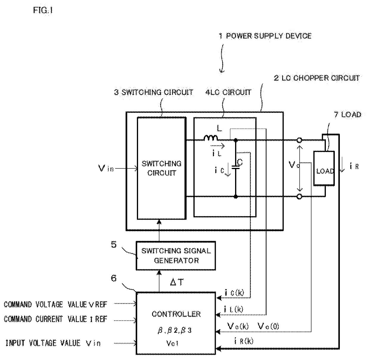
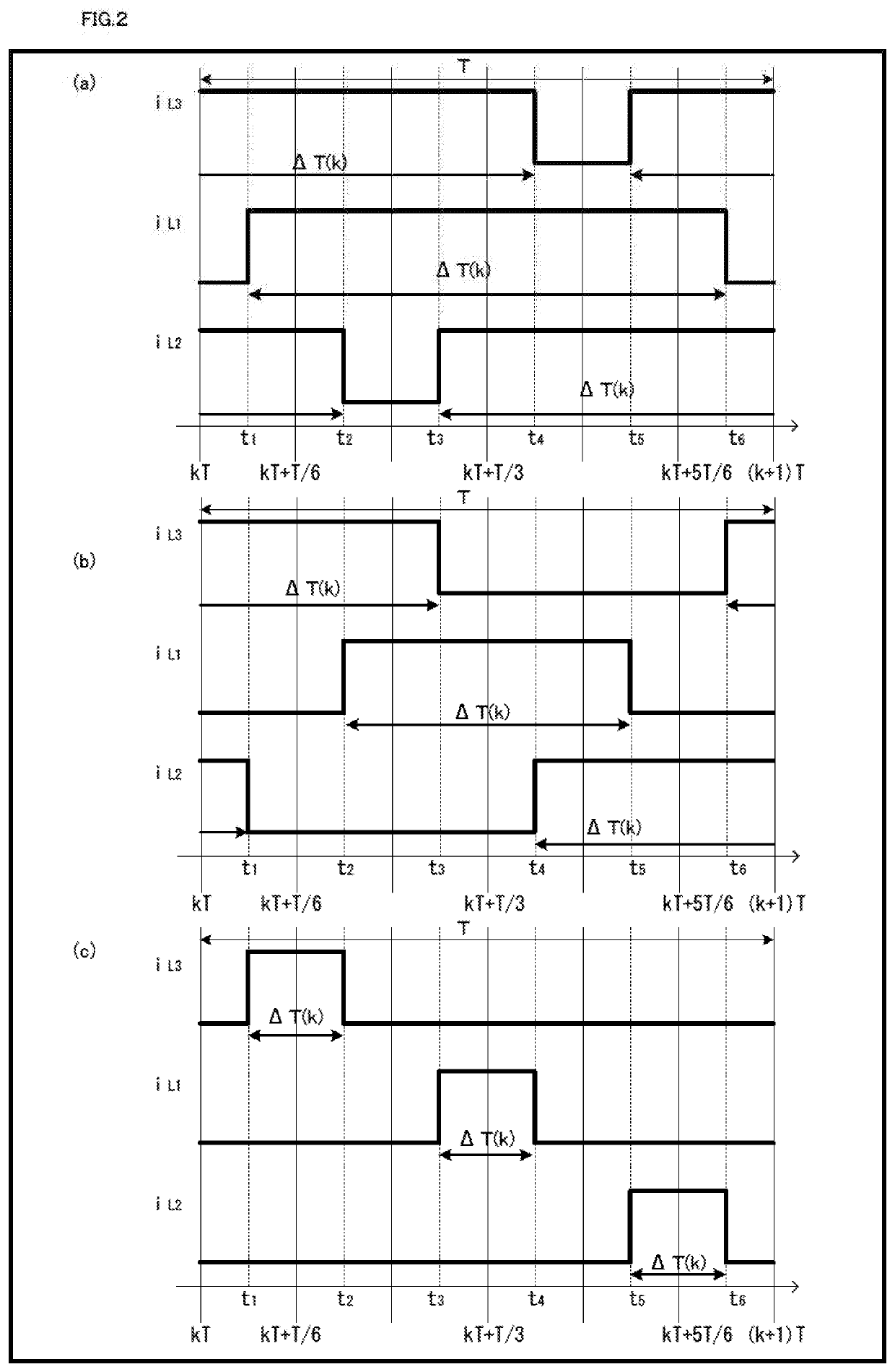
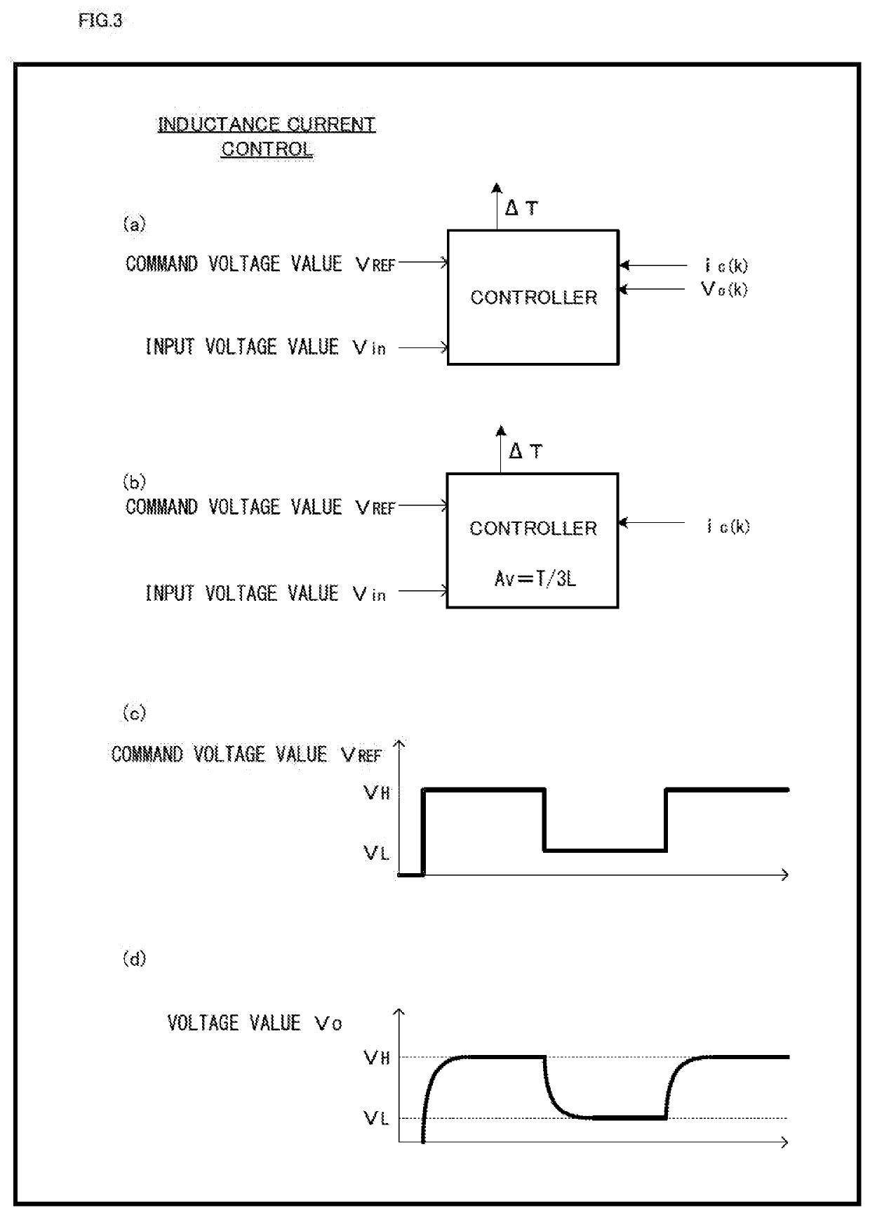
[0075]There will now be described a power supply device and a method for controlling the power supply device of the present invention, with reference to the accompanying drawings FIGS. 1 to 18. With reference to FIG. 1, a schematic configuration of the power supply device of the present invention will be described, and with reference to FIGS. 2 to 9, an example for controlling the power supply device of the present invention will be described. With reference to FIGS. 10 to 12, derivation of the pulse width ΔT(k) of the present invention will be described, and with reference to FIGS. 13 and 14, followability to a command value will be described. With reference to FIGS. 15 to 18, application examples of the power supply device of the present invention will be described.

(Schematic Configuration of the Power Supply Device of the Present Invention)

[0076]With reference to FIG. 1, a schematic configuration of the power supply device of the present invention will be described. The power sup...


PUM


Abstract

Provided is multi-phase interleaving control in a power supply device. In power control by the power supply device where the dead beat control is applied to the multi-phase interleaving, combined current of the multi-phase current values is used as control current in the multi-phase control based on the multi-phase interleaving, thereby achieving control independent of the number of the detectors and the control system independent of the number of phases, and further, this control current is used to perform constant current control, so as to prevent overshooting and undershooting. The power supply device has multi-phase interleaving control that performs multi-phase control using a plurality of phase current values, provided with an LC chopper circuit constituting a step-down chopper circuit that operates according to the multi-phase control of multi-phase interleaving, and a controller for performing step response control according to the multi-phase control of the LC chopper circuit.

Description

TECHNICAL FIELD[0001]The present invention relates to a power supply device and a method for controlling the power supply device.BACKGROUND ART[0002]With a proliferation of denser and more precise thin films generated by a process such as ashing and etching, manufacturing equipment such as semiconductor manufacturing equipment and flat-panel manufacturing equipment are demanded to have a function for supplying pulse-state RF power to a plasma load. In particular, it is being demanded to perform two-level pulse power control, i.e., wideband High / Low pulse power operation with a system where RF power is continuously variable, switched between “Low power” being minimum power that keeps plasma from being extinguished and “High power” that is required for generating thin films.[0003]A frequency band required by the High / Low pulse power operation is from 1 Hz to 50 kHz, for example. There are known some power supply devices for providing RF power, which employ class-A to class-E amplifier...

Claims


Application Information

Patent Timeline
Patent Type & Authority Applications(United States)
IPC IPC(8): H02M3/158
CPCH02M3/1584H02M2003/1586H02M3/135H02M3/155H02M1/0012H02M1/0009H02M3/1586H02M1/0043H02M3/158
Inventor YUZURIHARA, ITSUOOHMA, RYOSUKEKUNITAMA, HIROSHIHOSOYAMADA, YU
Owner KYOSAN ELECTRIC MFG CO LTD
Why Eureka
Try Eureka