Voltage filter and power conversion device

a voltage filter and power conversion technology, applied in the direction of feed-through capacitors, process and machine control, instruments, etc., can solve the problems of high frequency noise accompanying the rapid voltage change, and the malfunction of electronic devices, so as to improve the performance of the voltage filter

Active Publication Date: 2020-05-21
HITACHI LTD
View PDF9 Cites 3 Cited by
  • Summary
  • Abstract
  • Description
  • Claims
  • Application Information

AI Technical Summary

Benefits of technology

[0013]According to the embodiment, the performance of the voltage filter can be improved.

Problems solved by technology

Here, since a rapid voltage change or a rapid current change occurs when the switching element is turned on / off, high frequency noise accompanying the rapid voltage change or the rapid current change (surge voltage or surge current) is generated from the switching element.
As a result, an adverse effect which is represented by the malfunction of an electronic device (such as an ECU) disposed around the cable is exerted on the electronic device.

Method used


Image

  • Voltage filter and power conversion device
  • Voltage filter and power conversion device
  • Voltage filter and power conversion device

Examples


embodiment

Effect of Embodiment

[0087]Next, the effect of the present embodiment will be described.

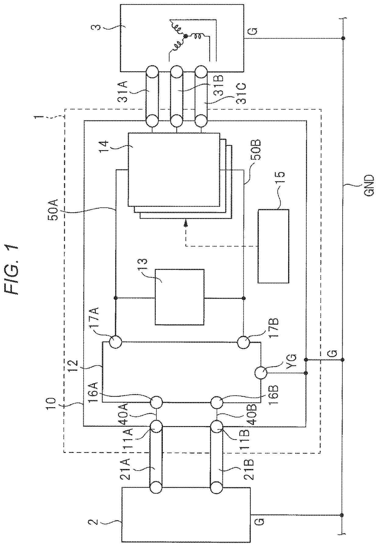
[0088]For example, in FIG. 8, a DC bus bar (not shown) and the semiconductor module 14 are disposed in the vicinity of the voltage filter 12A. The semiconductor module 14 includes, for example, the semiconductor element (power transistor) which is the switching element that constitutes the inverter. A noise current flows through the DC bus bar and the semiconductor module 14, and the temporally changing magnetic field (magnetic flux density) is generated from the noise current. The temporally changing magnetic field (magnetic flux density) generated from the semiconductor module 14 may adversely affect the voltage filter 12A disposed in the vicinity of the semiconductor module 14.

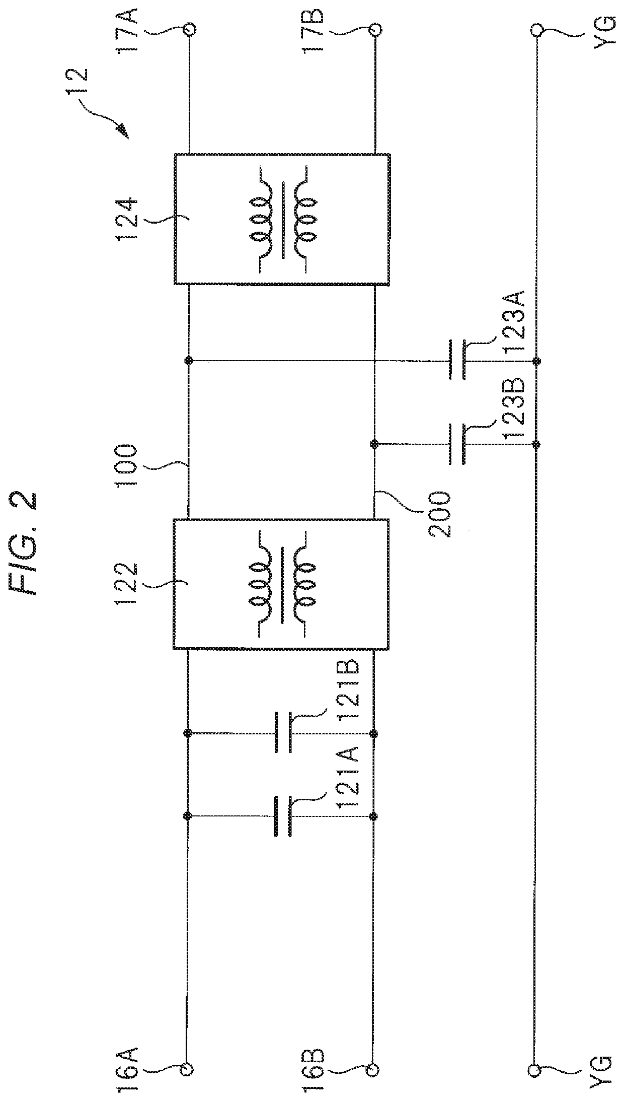
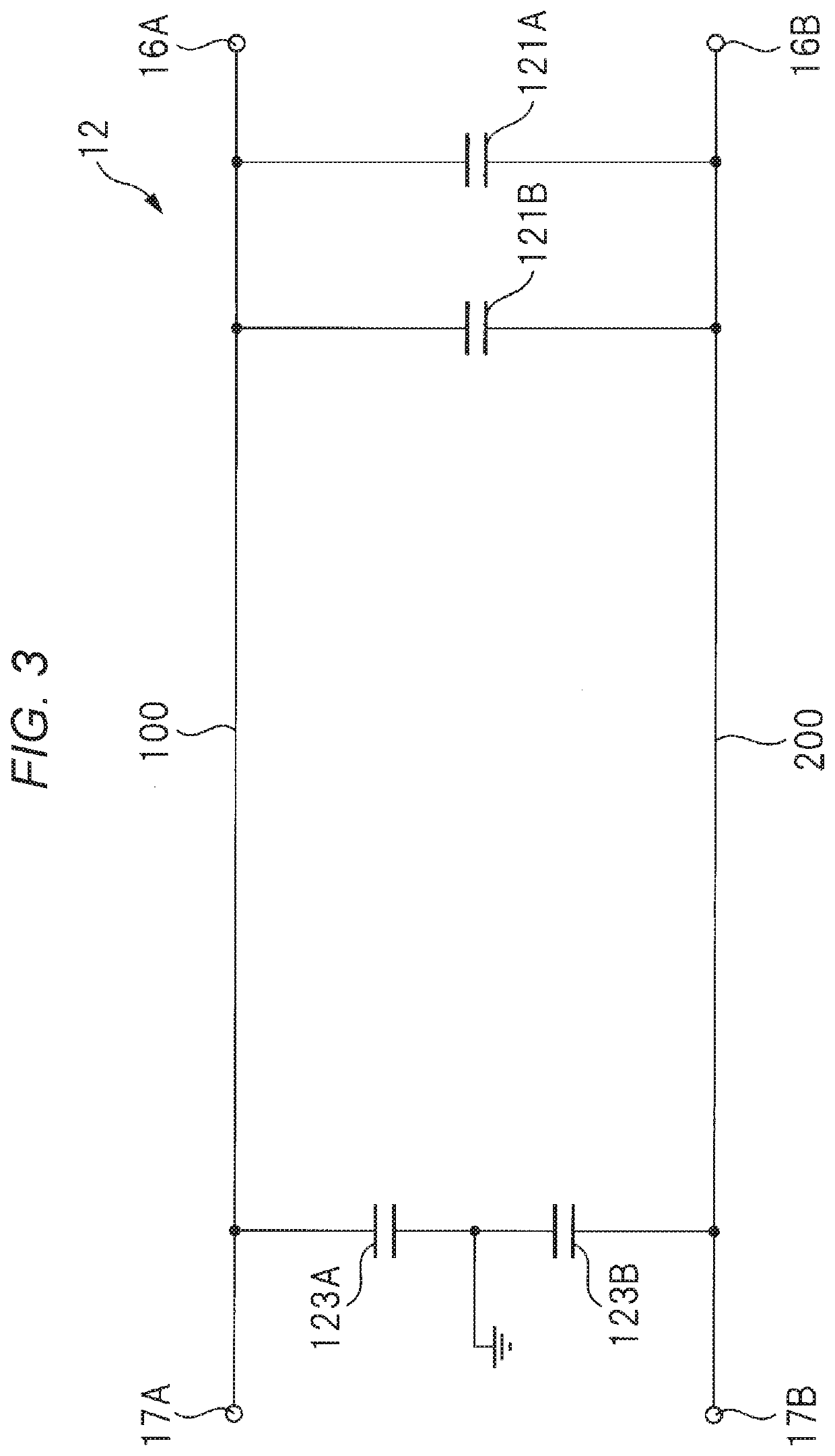
[0089]In this regard, for example, in the voltage filter 12 in the related art as shown in FIG. 5, a part of the temporally changing magnetic field penetrates the closed loop C1. As a result, the electromagnetic induction...


PUM


Abstract

To improve the performance of the voltage filter. Rather than reducing an area of a region surrounded by a closed loop formed in a voltage filter 12A, an induced electromotive force generated in the voltage filter 12A itself is reduced by forming a pair of a closed loop CA and a closed loop CB in which the directions of the generated induced electromotive forces are opposite to each other by making a wiring 100 (anode wiring) intersect a wiring 200 (cathode wiring).

Description

BACKGROUND OF THE INVENTION1. Field of the Invention[0001]The present invention relates to a voltage filter and a power conversion device.2. Description of the Related Art[0002]JP-A-2008-43023 (Patent Literature 1) describes a technique relating to a pair of bus bars intersecting with each other and disposed in parallel between a power module portion and a smoothing capacitor portion.[0003]JP-A-2012-178937 (Patent Literature 2) describes a technique for causing a first conductor plate and a second conductor plate to intersect halfway with respect to a driver circuit base plate.[0004]Japanese Patent No. 6113292 (Patent Literature 3) describes a technique in which wirings which connect X capacitors intersect an odd number of times.[0005]Japanese Utility Model Registration No. 3142501 (Patent Literature 4) describes a technique in which connection patterns that connect both ends of a smoothing capacitor with a pair of output terminals intersect on a single-sided printed wiring board.SU...

Claims


Application Information

Patent Timeline
Patent Type & Authority Applications(United States)
IPC IPC(8): H03H7/01H02M7/5395H02M3/156
CPCH03H7/0153H02M7/5395H02M3/156H01G4/35H01G4/38H01G4/40H02M1/126H02M7/003H03H7/427H02M1/123
Inventor TANIGUCHI, HITOSHIFUNATO, HIROKI
Owner HITACHI LTD
Why Eureka
Try Eureka