
Method of radiography of an organ of a patient

Pending Publication Date: 2020-05-28
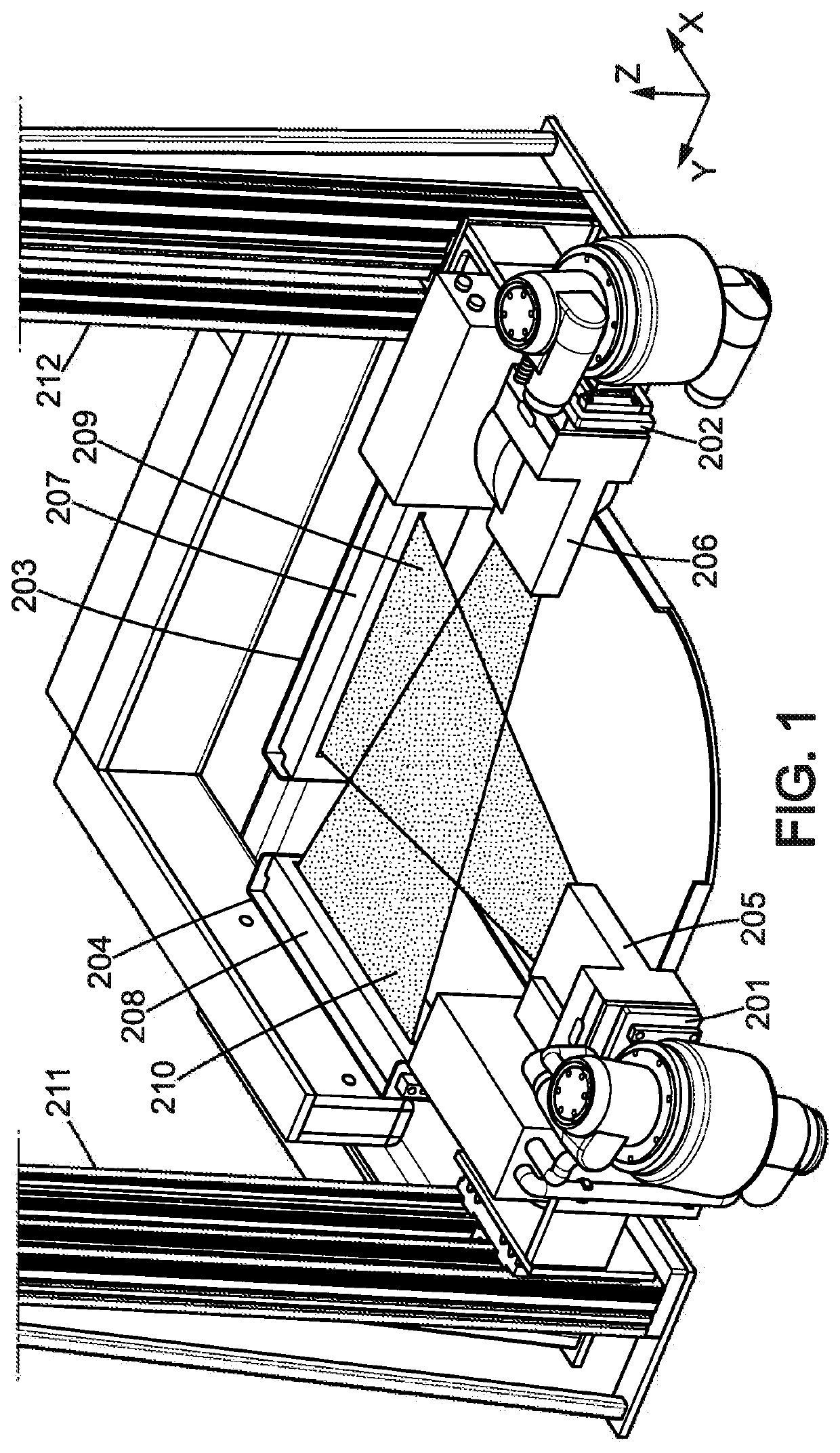
EOS IMAGING
View PDF0 Cites 3 Cited by
  • Summary
  • Abstract
  • Description
  • Claims
  • Application Information

AI Technical Summary

Benefits of technology

The invention aims to provide a radiology method that can simultaneously achieve both a high signal-to-noise ratio and a high cross-scattering rejection rate in patient organ imaging, regardless of their size or weight. Additionally, the method uses a vertical gap between the first and second sources to further reduce cross-scattering and improve image quality. This results in a better overall image quality, cancelling out most cross-scattering and self-scattering, while adding some added complexity.

Problems solved by technology

Overweight and obese patients have a larger and thicker body which will present specific challenges to methods of radiography of an organ of a patient, all the more that these overweight and obese patients are becoming more and more numerous.
But the maximum available dose rate of this system has also become a growing limitation to produce enough clinical quality images of overweight and obese patients, all the more that overweight and obese patients are nowadays very common patients.
One important problem to make some good clinical quality radiology images on overweight and obese patients is the big amount of scattered x-rays created while the direct x-ray beam is much attenuated.
Some scattering rejection grids are commonly used to solve this problem, but taken alone, their efficiency is not good enough, and therefore the dose on overweight and obese patients can become very high in order to get clinical quality images.
But the useful dose rate fraction to make the image becomes too small for overweight patients.
Some of the reasons are the limited output power of x-ray tubes and the very small collimation apertures.
However, high rejection rate was achieved thanks to narrow collimation thereby at the expense of lowering much the level of received radiation signal on the sensitive surfaces of the detectors.
Therefore, at least for some patient organs, when used with reasonably overweight patients, it was difficult, and when used with really overweight or even obese patients, it was not possible, to find a good compromise between a high rate of scattering rejection and simultaneously a sufficient level of received radiation signal on the sensitive surfaces of the detectors.
But, in this case, the output power of the x-ray tube and available collimation aperture of the detector would not be enough to cover the whole growing population of the varied morphologies among overweight and obese patients.
The aperture limitation will be directly linked with the loss of spatial resolution of the detector and the amount of scattered x-ray coming from both x-ray imaging frontal and lateral views.
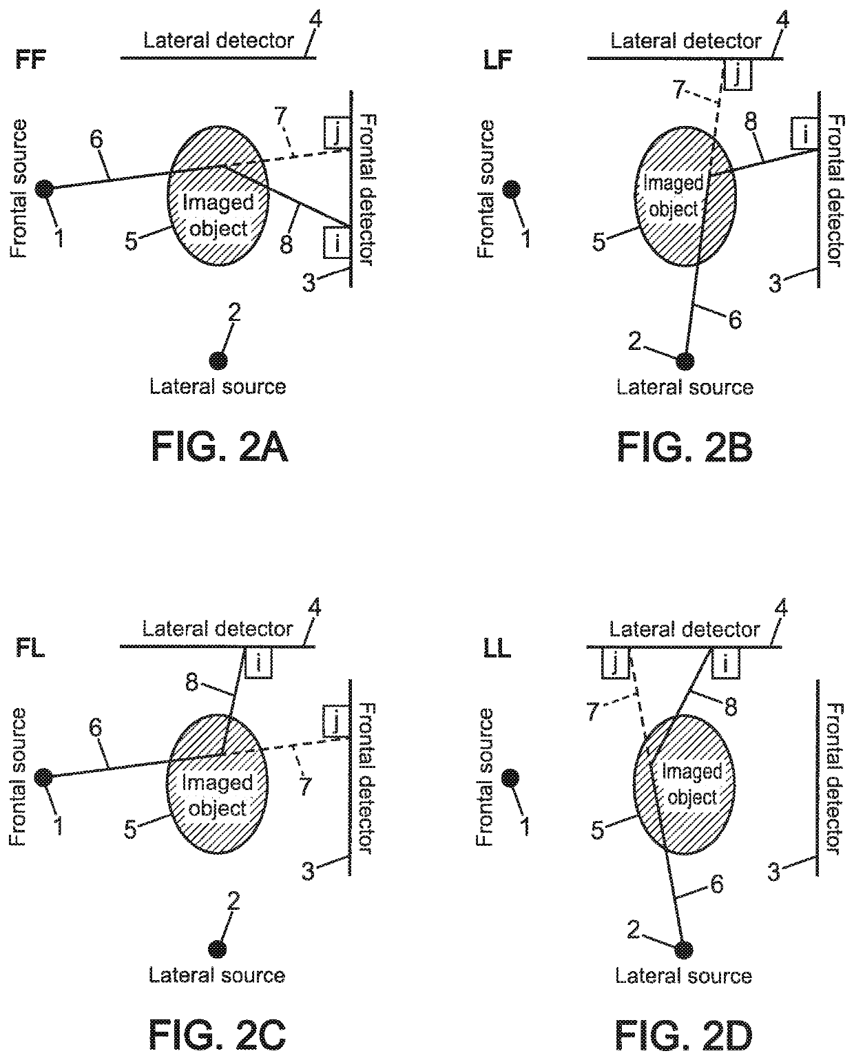
The use of coplanar simultaneous frontal and lateral x-ray views will create a specific problem of cross-scattering in addition to the self-scattering pollution of each view.

Method used


Image

  • Method of radiography of an organ of a patient
  • Method of radiography of an organ of a patient
  • Method of radiography of an organ of a patient

Examples


first embodiment

[0168]FIG. 6 shows an example of performing the steps of the method of radiography of an organ of a patient according to the invention, with use of scatter matrix and with scattered signal being under-sampled as compared to direct signal.

[0169]The different and successive steps of the scatter correction method to correct a given line of pixels on both frontal and lateral views with a preexisting matrix are hereby described.

[0170]In a step 30, frontal and lateral images are acquired.

[0171]In a step 31, those frontal and lateral images are denoised.

[0172]In a step 32, those frontal and lateral images are each divided into sub-images along vertical axis whose height is about 1 cm, representing some consecutive columns of aggregated image.

[0173]In a step 33, for each sub-image, the nearest combination of base ellipses within a predetermined family is found.

[0174]In a step 34, each sub-image is under-sampled, typically to 2 mm wide pixels.

[0175]In a step 35, either there is an under-samp...

second embodiment

[0190]FIG. 8 shows an example of performing the steps of the method of radiography of an organ of a patient according to the invention, with use of scatter matrix and with scattered signal at same sample rate as compared to direct signal.

[0191]The different and successive steps of the scatter correction method to correct a given line of pixels on both frontal and lateral views with a preexisting matrix are hereby described.

[0192]In a step 50, frontal and lateral images are acquired.

[0193]In a step 51, those frontal and lateral images are denoised.

[0194]In a step 52, those frontal and lateral images are each divided into sub-images along vertical axis whose height is about 1 cm, representing some consecutive columns of aggregated image.

[0195]In a step 53, for each sub-image, the nearest combination of base ellipses within a predetermined family is found.

[0196]A scatter matrix is chosen in the matrices database corresponding to the nearest combination of base ellipses. Here the databa...

third embodiment

[0253]FIG. 18 shows an example of performing the steps of the method of radiography of an organ of a patient according to the invention, with use of 3D avatar for patient specific modeling and with scattered signal being under-sampled as compared to direct signal.

[0254]The different and successive steps of the scatter correction method to correct a given line of pixels on both frontal and lateral views with a preexisting generic model of a patient are hereby described. This predetermined generic model is preferably common to all patients. If there is a predetermined set of generic models, there will be an additional preliminary step of choosing the most adapted generic model with respect to the patient corpulence.

[0255]In a step 120, frontal and lateral images are acquired.

[0256]In a step 121, a 3D (three dimensional) avatar is got both from the chosen generic model and from those raw frontal and lateral images. The raw frontal and lateral images are used to modify the generic model...


PUM


Abstract

Disclosed is a method of radiography of an organ of a patient, including: first and second vertical scanning being performed synchronously, wherein a computed correction is processed on both first and second raw images, on at least part of patient scanned height, for at least overweight or obese patients, so as to reduce, between first and second corrected images, cross-scattering existing between the first and second raw images, and wherein the computed correction processing on both the first and second raw images includes: a step of making a patient specific modeling, using as patient specific data therefore at least both first and second raw images, a step of determining a patient specific representation of radiation scattering by the patient specific modeling, a step of processing the patient specific radiation scattering representation on both the first and second raw images so as to get the first and second corrected images.

Description

FIELD OF THE INVENTION[0001]The invention relates to methods of radiography of an organ of a patient, as well as associated apparatus, in particular when the patient is an overweight or obese patient. In particular, this method of radiography is preferably a stereo-radiography method.BACKGROUND OF THE INVENTION[0002]The field of the invention deals with a double scanning, preferably stereo-radiographic, system and a method to optimize the radiation, preferably x-ray, scattering rejection and correction in order to acquire at least two simultaneous views, preferably frontal and lateral view images for low dose three dimensional reconstruction of an organ, preferably the skeleton, of patients for medical applications.[0003]This system and method are dedicated to be used within medical radiology devices including at least two radiations, preferably x-ray, transmissions based imaging capabilities. These capabilities will be based on for example at least an x-ray emission source emitting...

Claims


Application Information

Patent Timeline
IPC IPC(8): A61B6/00
CPCA61B6/032A61B6/544A61B6/5282A61B6/50A61B6/5247A61B6/466A61B6/5205A61B6/482A61B6/4233A61B5/055A61B6/5235A61B6/022A61B6/4014A61B6/5294G06T17/00G09B23/28G06T2207/10116G06T2207/20128
Inventor DESAUTE, PASCALMETZ, CAMILLE
Owner EOS IMAGING
Learn More