
Method and apparatus for scatter estimation in cone-beam computed tomography

a computed tomography and cone beam technology, applied in the field of estimation of scatter in imaging projection data, can solve the problems of large computational cost, and negative scattering on image quality, and achieve the effect of reducing the amount of prior information, reducing the cost of computation, and improving the accuracy of image quality

Active Publication Date: 2020-06-04
ACCURAY
View PDF0 Cites 7 Cited by
  • Summary
  • Abstract
  • Description
  • Claims
  • Application Information

AI Technical Summary

Benefits of technology

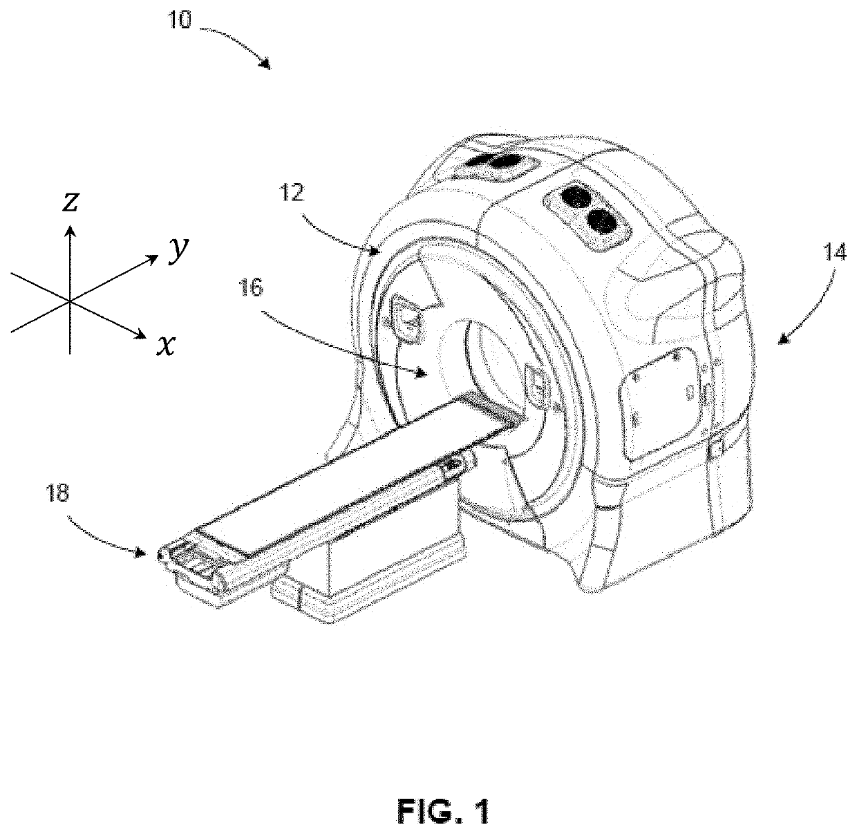
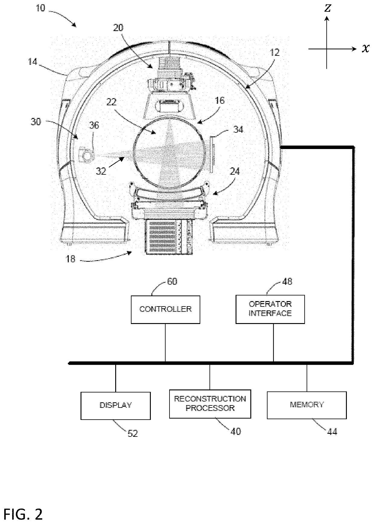
The patent describes an imaging apparatus that takes pictures using a rotating x-ray source and a detector. The apparatus has a tool that adjusts the shape of the x-ray beam so that the detector is exposed to the most direct radiation, while also blocking certain parts of the detector from exposure to the beam. The apparatus also collects data on the scattered x-rays and uses it to estimate the location of scattered particles in the primary exposed area. This helps improve the accuracy of the imaging process. The patent does not limit the use of specific features to one embodiment and can be used in other embodiments as well.

Problems solved by technology

Scatter can negatively impact image quality, including contrast and quantitative accuracy.
The former can be computationally costly, and the latter is generally considered as an open problem in the field.
However, these methods require a considerable amount of prior information on the data acquisition system and the patient, such that the effectiveness of these methods is highly dependent on the modeling accuracy.
Furthermore, they are also highly demanding in terms of computational power and time resulting in a significant negative impact on workflow and throughput.
However, they are sensitive to the kernel design, especially in terms of material and shape of the scanned object.
Drawbacks of such methods include wasted dose and / or degraded image quality.
However, this method is designed for a single circular scan (i.e., measurements in the primary and scatter regions occur concurrently during the same rotation), requires detector availability outside on both sides (in the longitudinal direction) of the collimation opening, and is limited in terms of estimation accuracy.

Method used


Image

  • Method and apparatus for scatter estimation in cone-beam computed tomography
  • Method and apparatus for scatter estimation in cone-beam computed tomography
  • Method and apparatus for scatter estimation in cone-beam computed tomography

Examples


Embodiment Construction

[0034]The following includes definitions of exemplary terms that may be used throughout the disclosure. Both singular and plural forms of all terms fall within each meaning.

[0035]“Component,” as used herein can be defined as a portion of hardware, a portion of software, or a combination thereof. A portion of hardware can include at least a processor and a portion of memory, wherein the memory includes an instruction to execute. A component may be associated with a device.

[0036]“Logic,” synonymous with “circuit” as used herein, includes but is not limited to hardware, firmware, software and / or combinations of each to perform a function(s) or an action(s). For example, based on a desired application or needs, logic may include a software-controlled microprocessor, discrete logic such as an application specific integrated circuit (ASIC), or other programmed logic device and / or controller. Logic may also be fully embodied as software.

[0037]“Processor,” as used herein includes, but is no...


PUM


Abstract

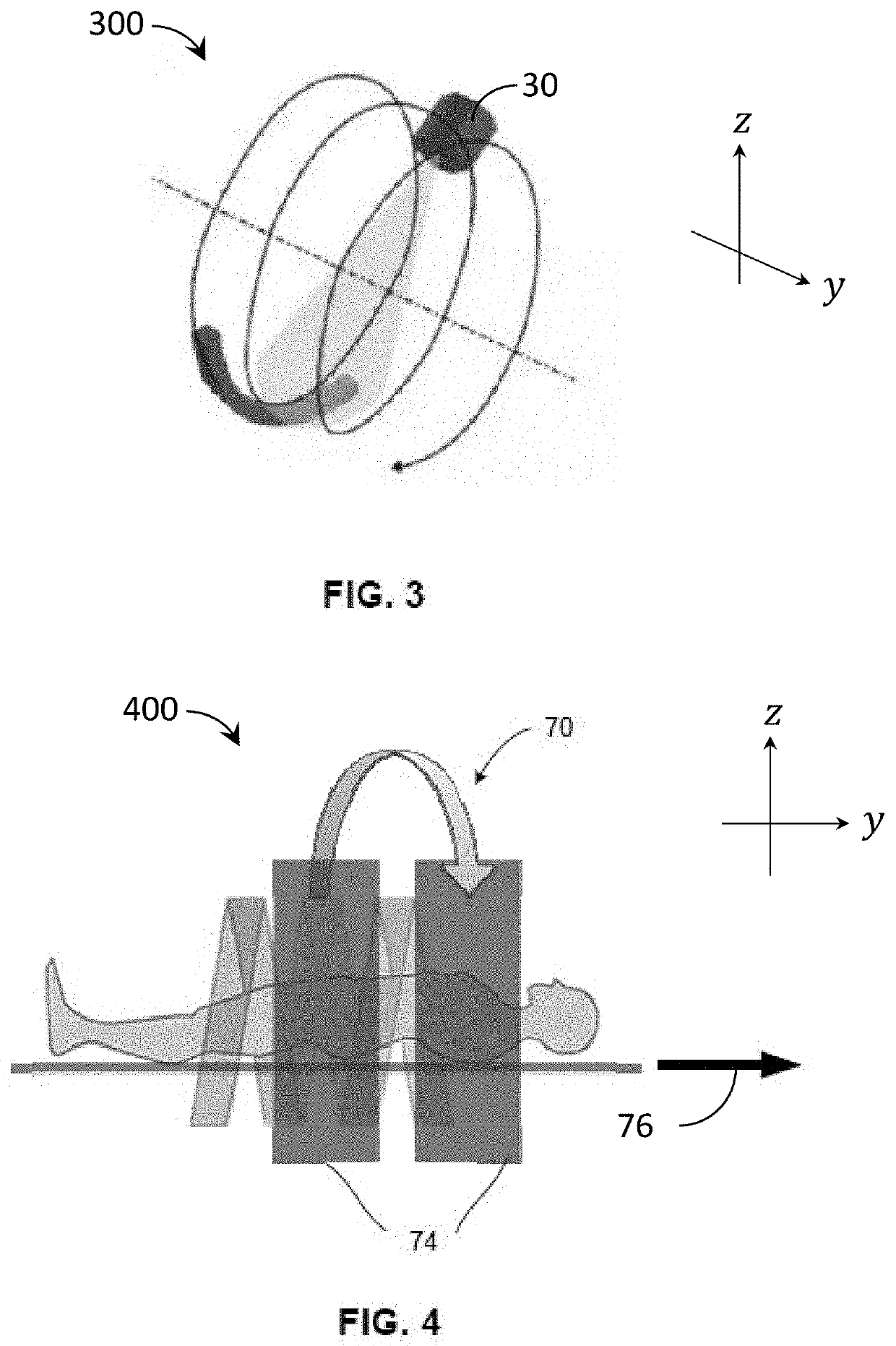
An x-ray imaging apparatus and associated methods are provided to receive measured projection data in a primary region and measured scatter data in a shadow region and determine an estimated scatter in the primary region during a current rotation based on the measured scatter data in the shadow region from a neighboring rotation. Coverage of the shadow region during the neighboring rotation overlaps the primary region during the current rotation. A beamformer is configured to adjust a shape of the radiation beam to create the primary and shadow regions on the detector, including an embodiment to follow the Tam-Danielson window during a helical scan.

Description

CROSS-REFERENCE TO RELATED APPLICATIONS[0001]This application claims the benefit of eleven U.S. provisional patent applications, including Ser. No. 62 / 773,712, filed Nov. 30, 2018 (Attorney Docket No. 38935 / 04001); Ser. No. 62 / 773,700, filed Nov. 30, 2018 (Attorney Docket No. 38935 / 04002); Ser. No. 62 / 796,831, filed Jan. 25, 2019 (Attorney Docket No. 38935 / 04004); Ser. No. 62 / 800,287, filed Feb. 1, 2019 (Attorney Docket No. 38935 / 04003); Ser. No. 62 / 801,260, filed Feb. 5, 2019 (Attorney Docket No. 38935 / 04006); Ser. No. 62 / 813,335, filed Mar. 4, 2019 (Attorney Docket No. 38935 / 04007); Ser. No. 62 / 821,116, filed Mar. 20, 2019 (Attorney Docket No. 38935 / 04009); Ser. No. 62 / 836,357, filed Apr. 19, 2019 (Attorney Docket No. 38935 / 04016); Ser. No. 62 / 836,352, filed Apr. 19, 2019 (Attorney Docket No. 38935 / 04017); Ser. No. 62 / 843,796, filed May 6, 2019 (Attorney Docket No. 38935 / 04005); and Ser. No. 62 / 878,364, filed Jul. 25, 2019 Attorney Docket No. 38935 / 04008). This application is also...

Claims


Application Information

Patent Timeline
Patent Type & Authority Applications(United States)
IPC IPC(8): A61B6/00A61N5/10A61B6/03
CPCA61B6/4441A61B6/483A61B6/4021A61N5/1067A61N2005/1095A61B6/035A61N2005/1091A61B6/4085A61B6/405A61N2005/1085A61N5/1082A61B6/4078A61B6/5235A61B6/542A61N5/1049A61N5/1081A61B6/50A61B6/5205A61B6/032A61B6/06A61B6/5258A61B6/5282A61B6/545A61B6/488A61B6/027A61B6/469A61B6/5264A61N5/1048A61N5/1071A61N2005/1061A61N5/1042G06T11/005A61B6/4233A61B6/482A61B6/4258A61B6/0487A61B8/488A61B6/025A61B6/5229A61B6/4417A61N5/107A61B6/08A61B6/4064G06T2211/424G06T2211/428G06T7/30A61B6/0407A61B6/4458G06T11/008G06T2207/10081G06T2210/41G06T2211/432A61B6/582A61B6/4014A61B6/481A61B6/484G06T2211/404G06T2211/412A61B6/4435A61B6/03A61B6/4028A61B6/541
Inventor YU, ZHICONGBAI, CHUANYONGJAIN, AMITGAGNON, DANIEL
Owner ACCURAY
Learn More