System for inerting at least one volume in an aircraft via at least one fuel cell

Inactive Publication Date: 2020-06-04
SAFRAN AEROTECHNICS SAS
View PDF0 Cites 2 Cited by
  • Summary
  • Abstract
  • Description
  • Claims
  • Application Information

AI Technical Summary

Benefits of technology

[0018]Another advantage is also that the fuel cell saves on air from the aircraft engines. T

Problems solved by technology

Lastly, the inert gas at the outlet of the current inerting system doe

Method used


Image

  • System for inerting at least one volume in an aircraft via at least one fuel cell

Examples


Embodiment Construction

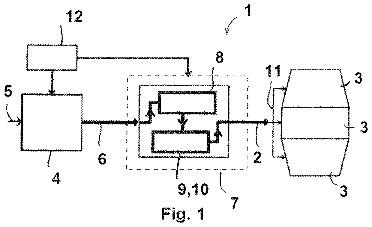
[0020]With reference to FIG. 1, which shows an inerting system (1) for injecting a flow of inert gas (2) into at least one volume (3), such as a fuel tank, a cargo compartment, an avionics bay, a hidden area, or sheathing for electric cables, in an aircraft or similar.

[0021]The inerting system (1) comprises a fuel cell (4) designed to be supplied with a reducing gas, such as hydrogen, and an oxidizing gas (5), such as air. In practice, the air originates from the passenger cabin of the aircraft, having been previously compressed by an electric compressor. At the outlet, the fuel cell (4) generates electricity, heat, water, and also oxygen-depleted humid air (6) destined to form the inert gas (2) to be injected into the volume (3) to be rendered inert. Depending on the aircraft, the mission profile, and the flight phase, the power of the fuel cell (4) is, for example, between 4 and 25 kW.

[0022]The fuel cell outlet is connected to means for drying (7) so that dry inert gas (2) can be ...


PUM


Abstract

A system for inerting at least one volume in an aircraft includes at least one generator of inert gas fed with compressed air originating from a passenger cabin, and means for distributing the inert gas into the volume to be rendered inert, which are connected to the generator of inert gas. According to the invention, the generator of inert gas comprises a fuel cell including an outlet of oxygen-depleted gas connected to means for drying said gas.

Description

TECHNICAL FIELD[0001]This system relates to the field of systems for inerting at least one volume, such as a fuel tank, cargo compartment, avionics bay, hidden area, or sheathing for electric cables, in an aircraft or similar.BACKGROUND[0002]In the field of aeronautics, an inerting system is known for generating an inert gas, such as nitrogen or any other inert gas, for example carbon dioxide, and for injecting said inert gas into fuel tanks for safety reasons in order to reduce the risk of explosion of said tanks.[0003]A conventional, prior art inerting system typically includes an on board inert gas generating system (OBIGGS) supplied with compressed air, for example, with compressed air diverted from at least one engine from a so-called intermediate pressure stage and / or a so-called high pressure stage based on a flight situation. The OBIGGS is connected to the airplane fuel tank and separates oxygen from the air.[0004]The OBIGGS is composed of at least one air separating module ...

Claims


Application Information

Patent Timeline
IPC IPC(8): B01D53/32H01M8/0662H01M8/04828B01D53/26A62C3/08A62C5/00A62C99/00B64D37/32B64D41/00
CPCB01D53/265H01M8/04843A62C5/006B64D2041/005B64D37/32A62C3/08B64D41/00B01D53/268A62C99/0018B01D53/326H01M8/0662B64D13/06B64D2013/0662B64D2013/0681Y02T50/50Y02T90/40Y02E60/50
Inventor GIROUD, NELLYMAILHET, PIERRICKVANDROUX, OLIVIER
Owner SAFRAN AEROTECHNICS SAS
Why Eureka
Try Eureka