System and method of controlling temperature of a medium by refrigerant vaporization and working gas condensation

a technology of working gas condensation and refrigerant vaporization, which is applied in the direction of refrigeration components, indirect heat exchangers, lighting and heating apparatus, etc., can solve the problems of adversely affecting batch quality, low overall heat generation, and inability to adapt to time and spatially dependent heat production characteristics, so as to improve temperature control, reduce system volume, and reduce the effect of temperature gradien

Active Publication Date: 2020-06-18
BIOTHERMIC PROCESS CONTROLS INC
View PDF1 Cites 0 Cited by
  • Summary
  • Abstract
  • Description
  • Claims
  • Application Information

AI Technical Summary

Benefits of technology

[0045]The present disclosure avoids these disadvantages by using a working gas located in shallow, horizontal tubes, and connected by a common space. The working gas is held at or close to the desired temperature of the system volume and its condensation is controlled such that the working gas condenses at this same temperature. Because condensed liquid in the horizontal tubes is removed quickly and the tube vapor spaces remain connected, each horizontal section then condenses at approximately the same pressure / temperature as the horizontal sections above and below.
[0046]Temperature control of the system volume is affected by control of the condensation of the working gas. The working gas, when at its condensation point, will release a large amount of energy per unit volume as it changes phases to liquid but will also release this energy at constant temperature. Thus any local system volume near the horizontal tubes is protected from falling below the condensation temperature of the working gas therein, as long as those tubes contain working gas.
[0047]The present disclosure provides passive, continual, and continuous protection against a decrease in system volume, set-point temperature. A temperature sensing element is no longer required to activate the heating system, as local working gas condensation adds heat as soon as it is required and near the spatial point of requirement. Additionally, a high temperature gradient for heating is not required, as heat transfer must no longer be accomplished rapidly and across large distances (e.g., container wall to container center). As local heat requirement varies, the local temperature differential between the system volume and working gas coil also varies, and heat will be added proportionally by a waiting mass of local working gas.
[0048]In summary, the systems and methods of the present disclosure improve significantly on traditional temperature control methods. The approach no longer risks unnecessarily heating the entire system volume based upon conditions near a local, temperature sensing element or failing to activate that heating system, when needed, based upon local conditions near the sensing element. The present disclosure also avoids the need to create large temperature gradients that may risk thermal heat shock of system contents. Furthermore, controlled cooling of the medium can be affected using the reaction's own endothermic heat requirement without risk of overshoot and the possibility of thermal cold shock of system contents. Benefits of improved temperature control include optimized reaction rates, reduced undesirable side-reactions, and improved consistency between batches for batch processes.

Problems solved by technology

Traditional cooling methods do not have the capability of adapting to the time and spatially dependent heat production characteristics of chemical and biochemical reactions, particularly those with low heat outputs.
Although these reactions can generate substantial instantaneous heat, the overall heat generated is low, and heat production values often vary significantly in time and space.
Failure to control the fermentation temperature of red wine may adversely affect batch quality.
Specifically, yeast may clump on floating skins, generate localized areas of high heat / accelerated metabolic activity, and die prematurely due to elevated, local temperatures.
These deaths then result in an insufficient yeast population to complete the conversion of all sugar in the tank or vessel (an incomplete / failed fermentation).
Furthermore, failure to control temperature during fermentation can alter the flavor of the wine, due to changes in yeast metabolic selectivity for production of volatile metabolites.
While this method can provide rapid cooling of a vessel volume, quickly offsetting the heat of reaction, unnecessary cooling may follow.
Similar temperature control challenges are observed when heating of a reaction vessel is desired via an external heating jacket with a variable flow of hot water or steam and a temperature control element submerged in the reaction vessel.
However, many common biological reactions, like ethanol production during beer fermentation, are not artificially agitated as the yeast naturally generates CO2, helping to homogenize the fermenting culture.
Artificial agitation also risks accidental oxidation of the beer during fermentation, possibly altering the flavor profile and reducing shelf-life.
The brewer thus must rely upon natural agitation but cannot be certain that the vessel cooling or heating system functions at optimal conditions due to lack of homogeneity in the fermenting volume.
Temperature extremes, either above or below the desired range, risk both generation of unwanted chemical byproducts (esters, diacetyls, fusel alcohols, etc.) and thermal shock of the yeast, which can lead to cellular damage, including premature death.

Method used


Image

  • System and method of controlling temperature of a medium by refrigerant vaporization and working gas condensation
  • System and method of controlling temperature of a medium by refrigerant vaporization and working gas condensation
  • System and method of controlling temperature of a medium by refrigerant vaporization and working gas condensation

Examples


Embodiment Construction

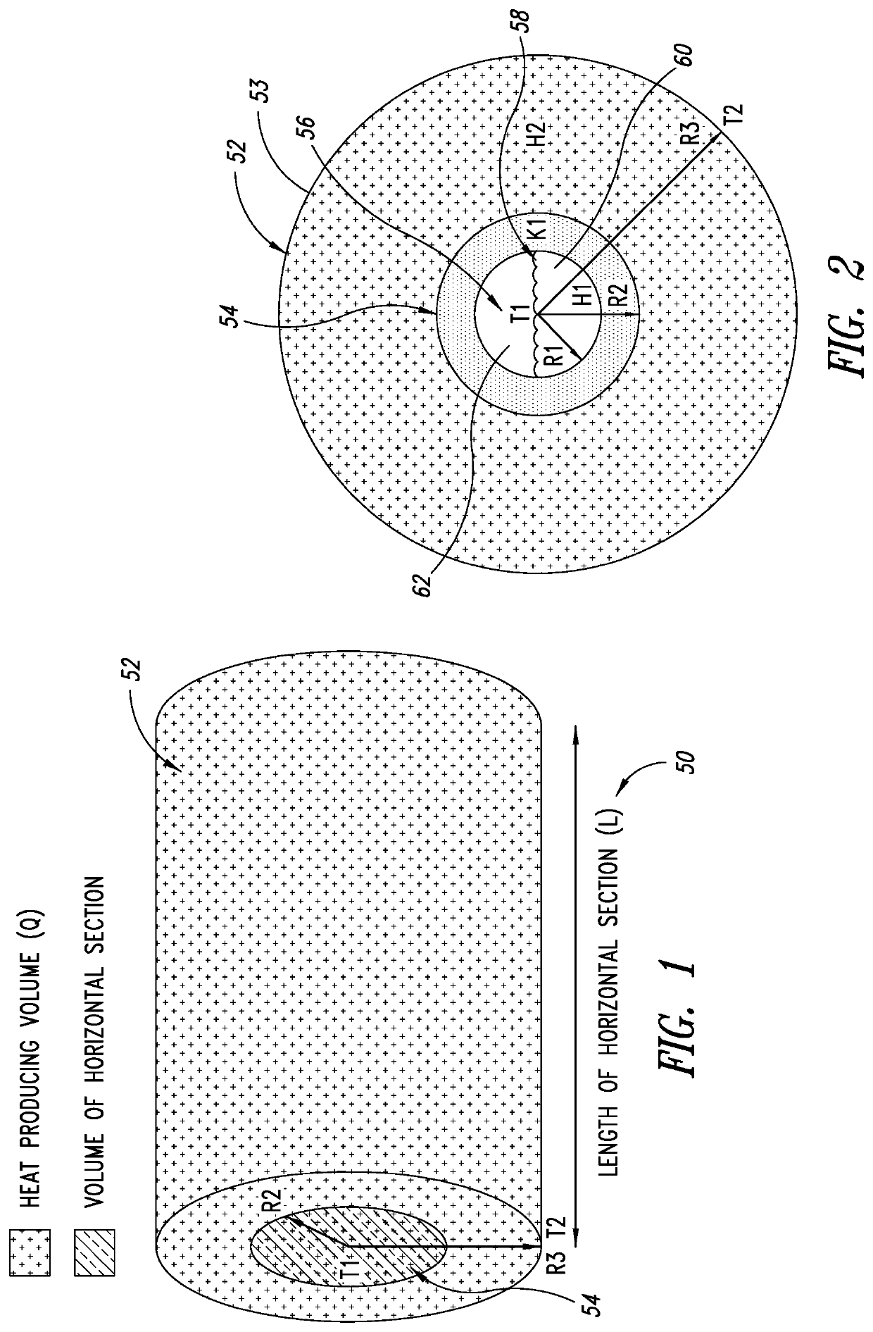
[0082]In the following description, certain specific details are set forth in order to provide a thorough understanding of various disclosed implementations. However, one skilled in the relevant art will recognize that implementations may be practiced without one or more of these specific details, or with other methods, components, materials, etc. In other instances, well-known structures associated with tanks or vessels, refrigerant, working gas, vaporization systems and vacuum systems, condensation systems, tubing, pipes, and coils have not been shown or described in detail to avoid unnecessarily obscuring descriptions of the implementations. Reference to “medium” is intended to include gas, liquid, solid, as well as gel and other states. Reference to “container” is intended to include, without limitation, tanks and vessels. In addition, reference to “pipe” or “tube” is intended to encompass conduits of various cross-sectional geometric configurations and conduits of any length un...


PUM


Abstract

A system and method of controlling temperature of a medium by refrigerant vaporization, or working gas condensation, or a combination of both, the system including a container, at least one a working gas reservoir having at least one reservoir section that includes a wall with an exterior surface structured to be thermally coupled with a volume of the medium in the container and to provide a volume of medium thermal coverage in the container, a condensation apparatus to provide regulation of working gas condensation in the reservoir, whereby the working gas reservoir forms a vapor space in each of the at least one reservoir section in response to receiving the working gas and to the condensation apparatus regulation of condensation to enable working gas condensation at or near a selected temperature of the volume of medium in the container that is thermally coupled to the respective reservoir section.

Description

BACKGROUNDTechnical Field[0001]The present disclosure is directed to temperature control of a medium and, more particularly, to controlling the temperature of the medium by localized temperature control of respective localized thermal volumes that constitute the medium according to properties of the medium.Description of the Related Art[0002]Temperature control is a fundamental requirement for successful chemical reaction engineering. Biological cells grow and produce products at an optimum temperature; likewise chemical catalysts, separations, crystallizations, evaporations, filtrations, polymerizations, isomerizations, and other reactions have specific operating temperatures which best achieve desired results.[0003]Traditional cooling methods do not have the capability of adapting to the time and spatially dependent heat production characteristics of chemical and biochemical reactions, particularly those with low heat outputs. Such reactions include ethanol and lactic acid ferment...

Claims


Application Information

Patent Timeline
Patent Type & Authority Applications(United States)
IPC IPC(8): F25B23/00F25B39/04
CPCF25B23/006F25B39/04C12G1/0213Y02E60/14F28D1/0213C12C11/006C12H1/22C12M41/18C12G1/00
Inventor ABELL, THOMAS U.
Owner BIOTHERMIC PROCESS CONTROLS INC
Why Eureka
Try Eureka