
Method of wire break detection

a technology of high impedance fault and detection method, which is applied in continuity testing, fault location by conductor type, instruments, etc., can solve problems such as potential fire hazard or human hazard, faults in the distribution network, and downed lines, and achieve complex machine learning algorithms

Active Publication Date: 2020-06-18
S&C ELECTRIC
View PDF0 Cites 16 Cited by
  • Summary
  • Abstract
  • Description
  • Claims
  • Application Information

AI Technical Summary

Benefits of technology

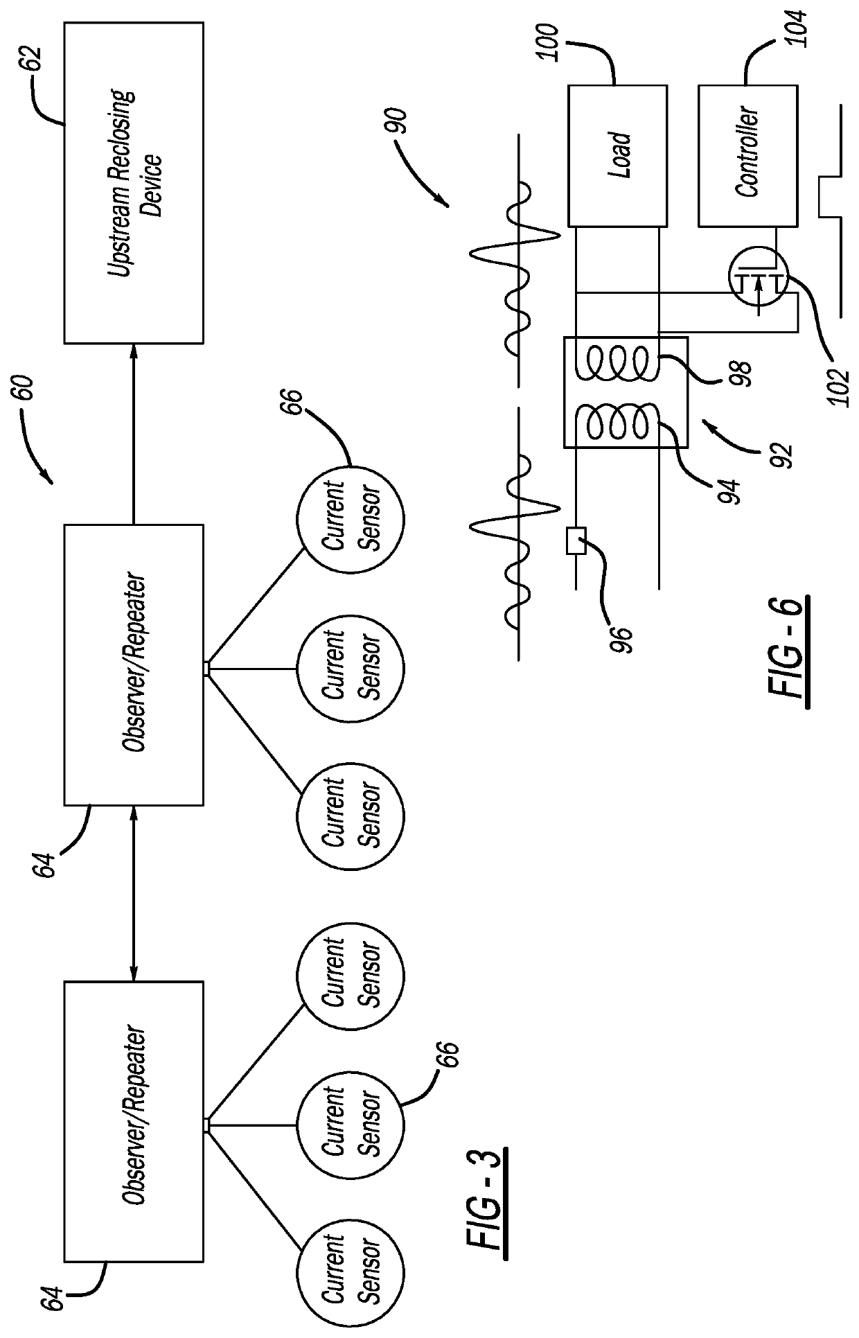
This patent describes a system and method for detecting a high impedance fault in an electrical line strung along and between utility poles, using current sensors and an observer / repeater device that compares current readings and alerts a recloser if a fault occurs. The current sensors may be powered by a temporary increase in current on the primary current carrying line if the current flow on the line is not sufficient to provide power for the sensor. The technical effects of this patent are improved detection and location of high impedance faults, which can help to prevent damage to equipment and reduce downtime for maintenance.

Problems solved by technology

Periodically, faults, such as a downed line, occur in the distribution network as a result of various things, such as animals touching the lines, lightning strikes, tree branches falling on the lines, vehicle collisions with utility poles, equipment failure, etc.
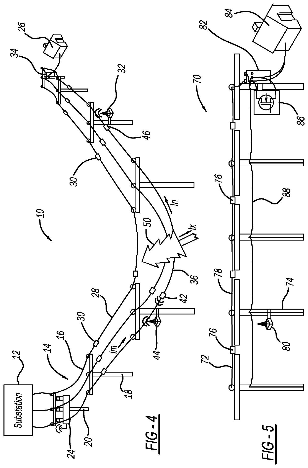
Faults may create an open circuit when a line breaks or a high impedance current flow when a line touches the ground or a tree, where the current flow is small and does not trigger an upstream recloser device to open, which creates a potential fire hazard or human hazard.
Often, these known techniques employ complex machine learning algorithms that use current and voltage measurements and that require a lot of machine power and constant reconfiguration when the load profile changes.

Method used


Image

  • Method of wire break detection
  • Method of wire break detection
  • Method of wire break detection

Examples


Embodiment Construction

[0014]The following discussion of the embodiments of the disclosure directed to a system and method for detecting a high impedance fault in an electrical power distribution network is merely exemplary in nature, and is in no way intended to limit the invention or its applications or uses.

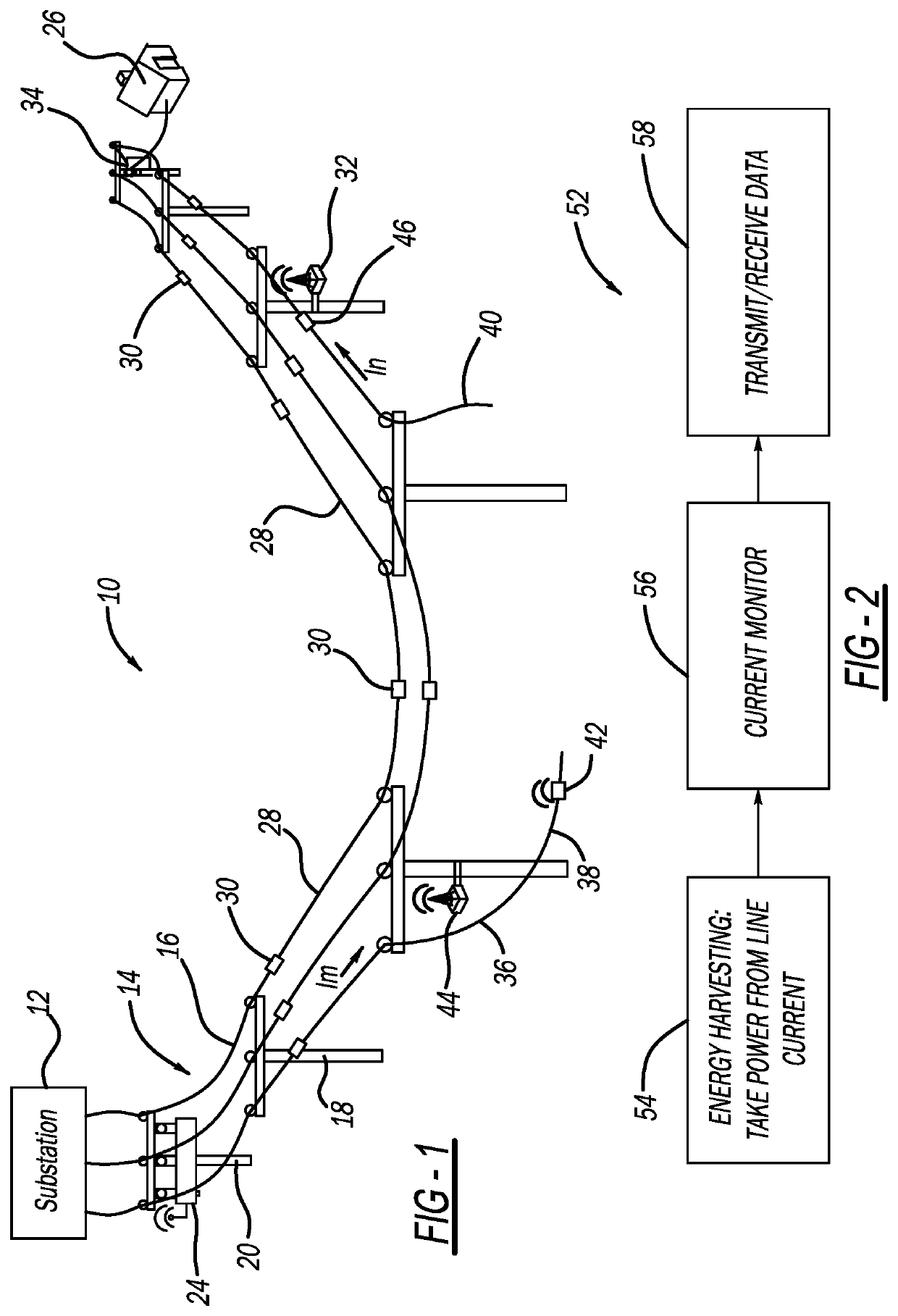
[0015]FIG. 1 is an illustration of an electrical power distribution network 10 including an electrical substation 12 that steps down high voltage power from a high voltage power line (not shown) to medium voltage power, and a three-phase feeder 14 having three single phase power lines 16 that receive the medium voltage power signal from the substation 12, where the lines 16 are suspended along and between a series of utility poles 18. One pole 20 of the utility poles 18 includes a recloser 24 that has a relay or interrupter switch (not shown) for each line 16 to allow or prevent current flow therethrough. The recloser 24 also includes sensors (not shown) for measuring the current and voltage of the ...


PUM


Abstract

A system and method for detecting a high impedance fault in an electrical line strung along and between utility poles, where the line is part of an electrical power distribution network. A current sensor is provided on each line segment between the utility poles, where each current sensor harvests power therefrom and continuously monitors the current flow on the line segment. An observer / repeater device is provided on a number of the poles and each is in communication with certain select ones of the current sensors to receive the current measurements therefrom. One of the observer / repeater devices compares the current readings transmitted to it from the subordinate current sensors, and if a violation of Kirchhoff's current law exists, an indication of a high impedance fault occurs, where the observer / repeater device relays the current irregularity to an upstream recloser to take appropriate action.

Description

CROSS-REFERENCE TO RELATED APPLICATION[0001]This application claims the benefit of priority from the U.S. Provisional Application No. 62 / 778,481, filed on Dec. 12, 2018, the disclosure of which is hereby expressly incorporated herein by reference for all purposes.BACKGROUNDFiled[0002]The present disclosure relates generally to a system and method for detecting a fault in an electrical power distribution network and, more particularly, to a system and method for detecting a high impedance fault in an electrical power distribution network.Discussion of the Related Art[0003]An electrical power distribution network, often referred to as an electrical grid, typically includes a number of power generation plants each having a number of power generators, such as gas turbine engines, nuclear reactors, coal-fired generators, hydro-electric dams, etc. The power plants provide a high voltage AC signal on high voltage transmission lines that deliver electrical power to a number of substations t...

Claims


Application Information

Patent Timeline
IPC IPC(8): G01R19/25G01R31/08G01R19/00
CPCG01R19/2513G01R31/085G01R19/0092G01R31/54
Inventor LAKIROVICH, KONSTANTINDE YOUNG, CHRISTOPHERFRENCH, JOHN
Owner S&C ELECTRIC
Learn More