Transmission line device

a transmission line and line technology, applied in the direction of waveguide devices, waveguide type devices, printed circuit aspects, etc., can solve the problems of reducing the service life of the transmission line, and reducing the risk of peeling or disconnection. , to achieve the effect of preventing or reducing the poor bonding at the joint portion of the transmission lin

Active Publication Date: 2020-06-18
MURATA MFG CO LTD
View PDF0 Cites 3 Cited by
  • Summary
  • Abstract
  • Description
  • Claims
  • Application Information

AI Technical Summary

Benefits of technology

[0006]Preferred embodiments of the present invention provide transmission line devices in each of which poor bonding at the joint portion between the transmission lines is reduced or prevented.

Problems solved by technology

However, in a structure in which the transmission lines are joined, stress is easily applied to the joint portion at the time of joining or after joining, and there is a risk of peeling or disconnection.
For this reason, there is a problem in that manufacturing process management for limiting the stress becomes complicated and the usage environment is restricted.

Method used


Image

  • Transmission line device
  • Transmission line device
  • Transmission line device

Examples


first preferred embodiment

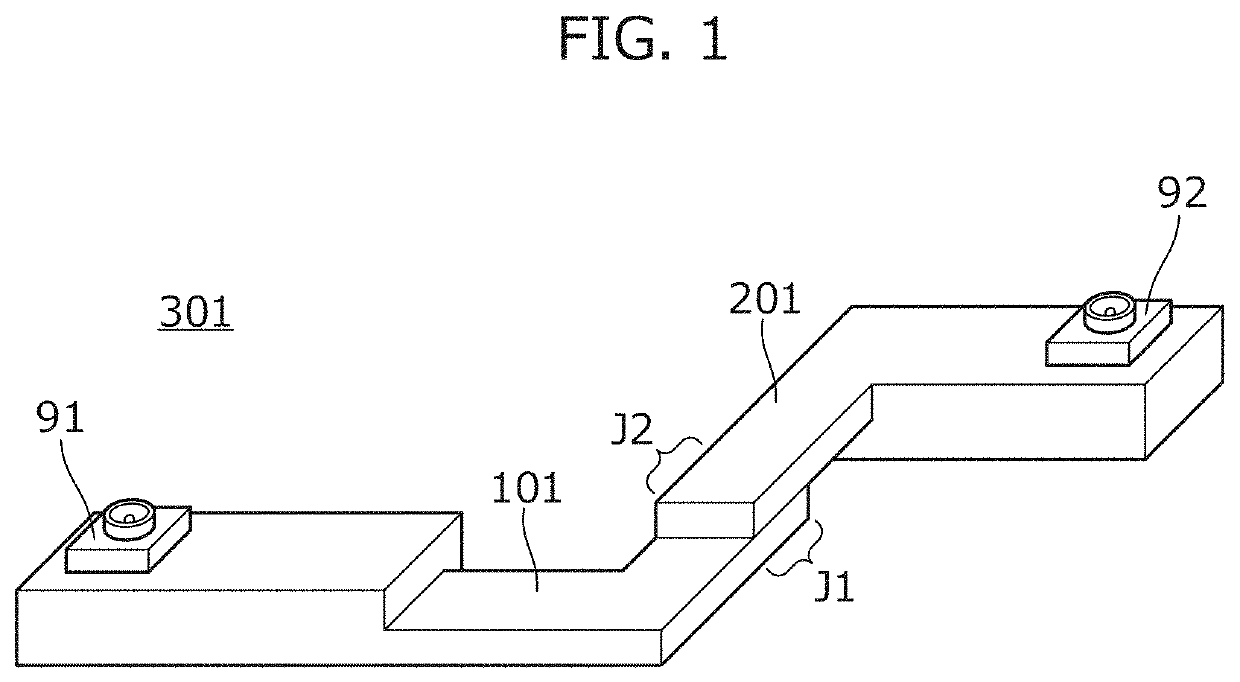
[0028]FIG. 1 is a perspective view of a transmission line device 301 according to a first preferred embodiment of the present invention. In the transmission line device 301, a first transmission line 101 and a second transmission line 201 are joined.

[0029]The first transmission line 101 includes a joint portion J1 with the second transmission line 201, and the second transmission line 201 includes a joint portion J2 with the first transmission line 101. That is, the transmission line device 301 is defined by joining the joint portion J1 of the first transmission line 101 and the joint portion J2 of the second transmission line. Coaxial connectors 91 and 92 are mounted on the transmission line device 301. The transmission line device 301 is used as a cable including the coaxial connectors 91 and 92.

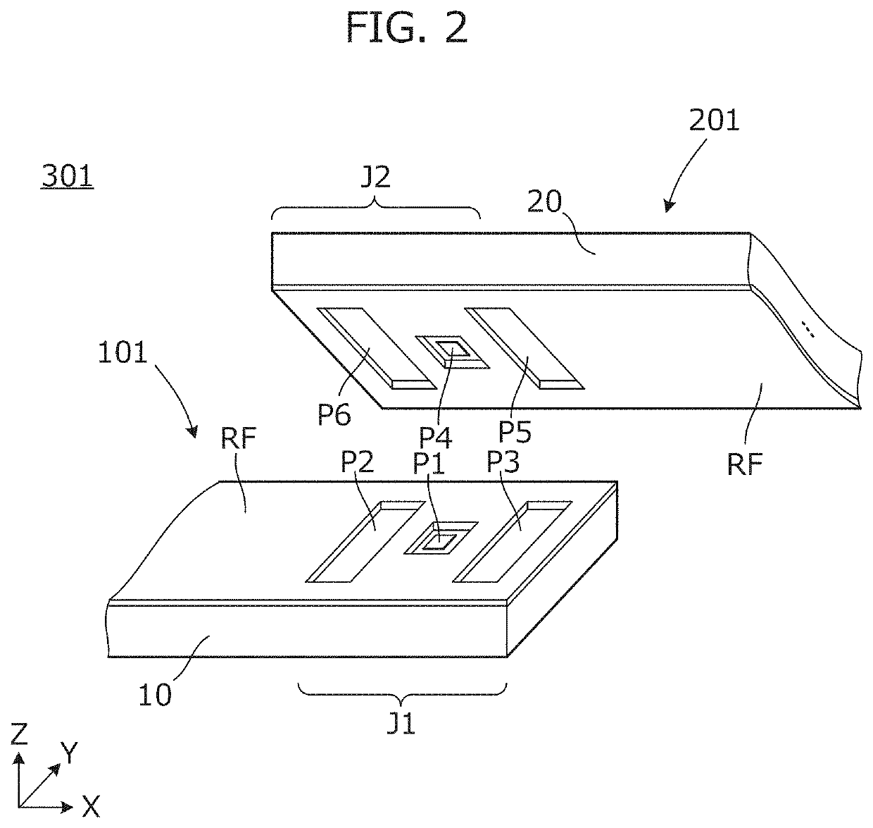
[0030]FIG. 2 is a partial perspective view showing a structure of the joint portion between the first transmission line 101 and the second transmission line 201. FIG. 2 shows a state befor...

second preferred embodiment

[0060]In a second preferred embodiment of the present invention, an example in which the configuration of the conductor pattern at the joint portion between the first transmission line and the second transmission line is different from that in the first preferred embodiment will be described.

[0061]FIG. 7 is a perspective view of a transmission line device 302 according to the second preferred embodiment. FIG. 7 shows a state before a first transmission line 102 and a second transmission line 202 are joined. In the transmission line device 302, the first transmission line 102 and the second transmission line 202 are joined.

[0062]The first transmission line 102 includes a plurality of stacked first insulating substrates and a first conductor pattern located on each of the first insulating substrates. The first conductor pattern includes three first signal conductor patterns, a plurality of first ground conductor patterns, first electrode pads P11, P12, and P13 that are respectively el...

third preferred embodiment

[0077]In a third preferred embodiment of the present invention, an example in which the configuration of the conductor pattern at the joint portion between the first transmission line and the second transmission line is different from those in the first and second preferred embodiments will be described.

[0078]FIG. 10 is a perspective view of a transmission line device 303 according to the third preferred embodiment. FIG. 10 shows a state before a first transmission line 103 and a second transmission line 203 are joined. In the transmission line device 303, the first transmission line 103 and the second transmission line 203 are joined.

[0079]The first transmission line 103 includes two first signal conductor patterns, first electrode pads P11 and P12 that are respectively electrically connected to the first signal conductor patterns, and a second electrode pad P2 and a third electrode pad P3 that are portions of the first ground conductor pattern.

[0080]The second transmission line 20...


PUM

PropertyMeasurementUnit
stressaaaaaaaaaa
insulatingaaaaaaaaaa
joint strengthaaaaaaaaaa

Abstract

A transmission line device includes first and second transmission lines. The first transmission line includes a first electrode pad that is electrically connected to a first signal conductor pattern, and a second electrode pad and a third electrode pad that are portions of a first ground conductor pattern. The second transmission line includes a fourth electrode pad that is electrically connected to a second signal conductor pattern, and a fifth electrode pad and a sixth electrode pad that are portions of a second ground conductor pattern. The first electrode pad is between the second electrode pad and the third electrode pad, and the fourth electrode pad is between the fifth electrode pad and the sixth electrode pad. The second electrode pad and the third electrode pad are larger than the first electrode pad, and the fifth electrode pad and the sixth electrode pad are larger than the fourth electrode pad.

Description

CROSS REFERENCE TO RELATED APPLICATIONS[0001]This application claims the benefit of priority to Japanese Patent Application No. 2017-254831 filed on Dec. 28, 2017 and is a Continuation Application of PCT Application No. PCT / JP2018 / 046406 filed on Dec. 17, 2018. The entire contents of each application are hereby incorporated herein by reference.BACKGROUND OF THE INVENTION1. Field of the Invention[0002]The present invention relates to a transmission line including an insulating substrate and a conductor pattern, and particularly, to a transmission line device in which a plurality of transmission lines are connected.2. Description of the Related Art[0003]International Publication No. WO2014 / 069061 (A1) discloses that a transmission line having a complicated shape is defined by joining pieces having a multilayer substrate structure including a transmission line.[0004]As in a transmission line described in International Publication No. WO2014 / 069061 (A1), when individually produced trans...

Claims


Application Information

Patent Timeline
Patent Type & Authority Applications(United States)
IPC IPC(8): H01P3/08H01P1/04H05K3/36H05K1/11
CPCH01P3/088H01P1/04H05K2201/0141H05K1/111H05K3/363H01P5/028H01P3/081H01P3/085H01P3/082H01P1/047
Inventor ARAKI, SHINICHI
Owner MURATA MFG CO LTD
Why Eureka
Try Eureka