Unlock instant, AI-driven research and patent intelligence for your innovation.
Management of the number of active power cells of a variable speed drive
Active Publication Date: 2020-06-18
SCHNEIDER TOSHIBA INVERTER EUROPE SAS
View PDF3 Cites 0 Cited by
Summary
Abstract
Description
Claims
Application Information
AI Technical Summary
This helps you quickly interpret patents by identifying the three key elements:
Problems solved by technology
Method used
Benefits of technology
Benefits of technology
The patent text describes a new solution for improving the performance and lifespan of variable speed drives. Unlike previous solutions, this approach does not set a specific number of active power cells, which reduces power cell losses, improves the thermal state of the drive, and protects the motor from overvoltage. The solution also ensures homogeneous ageing of the power cells, which increases their service life.
Problems solved by technology
Furthermore, when a high voltage is required at the output of the variable speed drive, in a configuration comprising N power cells, bypassing one of them causes a voltage level to drop, and the system then operates in degraded mode and is not able to supply a full voltage.
Method used
Image
Click on the blue label to locate the original text in one second.
Reading with bidirectional positioning of images and text.
Examples
first embodiment
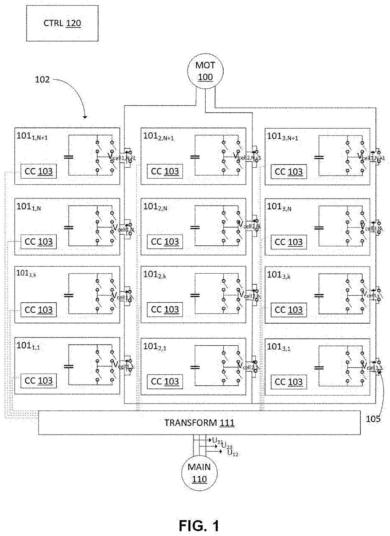
[0093]According to the invention, illustrated with reference to FIG. 4, the change of the number of active power cells is synchronized between the processor 300 and the FPGA 301. FIG. 4 illustrates the control signals when changing from a configuration in which three power cells 101 are active to a configuration in which two power cells 101 are active, for a given phase, at the time 404. Such configurations of course depend on the situation and are given only by way of illustration. FIG. 4 corresponds to control signals for a single phase out of the three phases supplying power to the motor 100 in FIG. 1.
[0094]In the previous configuration with three active power cells 101, the triangular-wave signals 401, 402 and 403 are generated by the FPGA 301 for three power cells 101 of the first phase.
[0095]These triangular-wave signals are associated with respective reference control voltages Vref1,1, Vref1,2 and Vref1,3 in order to compare and generate PWM control orders to be sent to the p...
second embodiment
[0103] only the FPGA 301 adapts its operation so as to reduce the number of active power cells 101, without this impacting the operation of the processor 300.
[0104]The FPGA 301, in a preceding phase, thus supplies the triangular-wave signals 501 to 503 associated respectively with respective reference control voltages Vref1,1, Vref1,2 and Vref1,3.
[0105]At the time 504, a modification of the number of active power cells 101 from three to two is determined, for example by virtue of receiving a new speed command and / or calculating a new reference motor voltage.
[0106]The period TDSP of the processor 300 is not modified and the triangular-wave signals thus remain offset by 2π / 3.
[0107]The FPGA 301 recalculates the values Vref1,1 and Vref1,2 so as to produce the target output voltage of the variable speed drive, and sets the value Vref1,3 to zero. The duty cycle applied by the power cell 1011,3 is therefore equal to 0, and the voltage at the output of this power cell 1011,3 is zero. The po...
PUM
Abstract
A method for controlling a variable speed drive supplying power to an electric motor, the variable speed drive comprising a plurality of at least Ni low-voltage power cells connected in series, comprising:upon reception of a speed command, determining a number Mi of cells sufficient to supply power to the motor at a target voltage V that is determined based on the speed command; andactivating the Mi power cells from among the Ni power cells, and deactivating the Ni-Mi other power cells in order to supply power to the motor in accordance with the speed command.
Description
TECHNICAL FIELD OF THE INVENTION[0001]The invention relates to the management of a variable speed drive responsible for supplying power to an electrical device, such as for example an electric motor.PRIOR ART[0002]In a power topology, a high voltage is supplied by a variable speed drive by placing a certain number of low-voltageconverters in series (which are then called power cells). Controlling these power cells makes it possible to supply a voltage at several levels, or a multilevel voltage, each power cell adding a voltage that makes it possible to achieve successive voltage levels.[0003]In accordance with European standards, low voltages are understood to mean voltages of between 0 and 1000 volts in AC voltage operation and between 0 and 1500 volts in DC voltage operation. High voltages are understood to mean voltages greater than 1000 volts in AC voltage operation and greater than 1500 volts in DC voltage operation.[0004]The variable speed drive may for example comprise N pow...
Claims
Application Information
Patent Timeline
Application Date:The date an application was filed.
Publication Date:The date a patent or application was officially published.
First Publication Date:The earliest publication date of a patent with the same application number.
Issue Date:Publication date of the patent grant document.
PCT Entry Date:The Entry date of PCT National Phase.
Estimated Expiry Date:The statutory expiry date of a patent right according to the Patent Law, and it is the longest term of protection that the patent right can achieve without the termination of the patent right due to other reasons(Term extension factor has been taken into account ).
Invalid Date:Actual expiry date is based on effective date or publication date of legal transaction data of invalid patent.
IPC IPC(8): H02P27/08
CPCH02P27/08H02M5/458H02P27/14H02M7/4835H02P27/06
Inventor FRAPPE, EMMANUELMALRAIT, FRANÇOISDEVOS, THOMAS



