
Ion mill shutter system

Inactive Publication Date: 2006-12-05
SEAGATE TECH LLC
View PDF18 Cites 0 Cited by
  • Summary
  • Abstract
  • Description
  • Claims
  • Application Information

AI Technical Summary

Benefits of technology

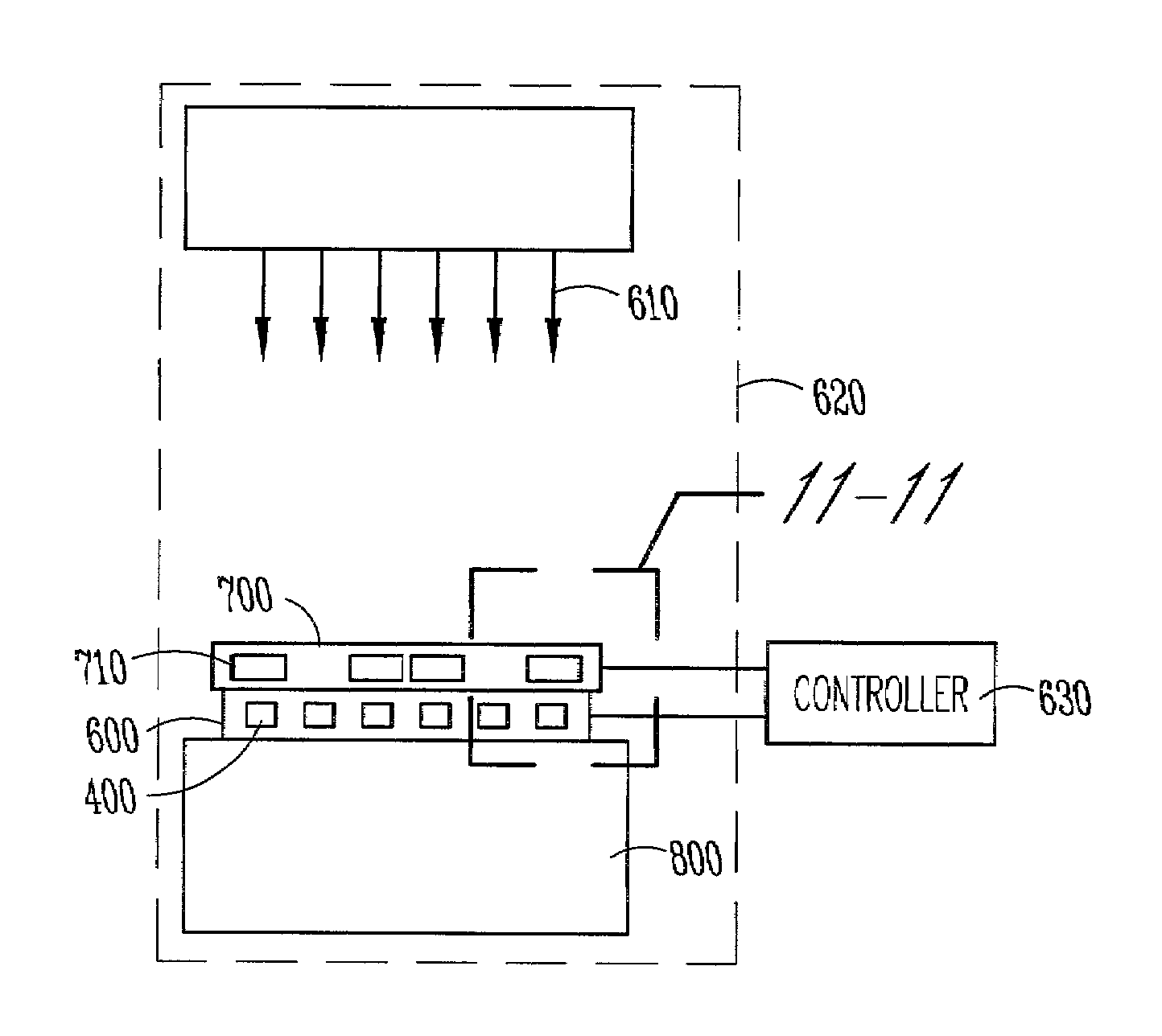
[0010]A device of the present invention for use during a semiconductor fabrication process includes a target and a mechanism for covering a portion of a target to prevent exposure of the portion of the target from the semiconductor fabrication process while an uncovered portion remains subjected to the semiconductor process. There is also a method used with the device.
[0014]Advantageously, the method and apparatus allows for careful control of the dimensions of an MR element or set of MR elements so that the signal output of each MR element can be within a selected, optimized range. The method and apparatus is both quick and reliable, such that the method and apparatus can be used in production of MR elements for disc drives. As a result of the ability to control dimensions or a particular dimension of the MR element, information stored at higher areal density can be reliably detected or read. Yet another advantage is that MR elements in a population can be made to be more uniform across a population of MR elements. In other words, the standard deviation of the MR elements is reduced that enhances the ability to introduce higher capacity disc drives using this technology. Thus, disc drives capable of still further increases in storage capacity can be produced at the manufacturing level.

Problems solved by technology

This manufacturing process has problems.
The initial steps of forming the MR elements using semiconductor fabrication techniques does not produce MR elements having uniform stripe heights.
Generally, there is no way to move the mask during a semiconductor process.
Still another problem associated with the manufacturing process is that feedback as to the stripe height or resistivity of the MR element is not obtained during manufacture.

Method used


Image

  • Ion mill shutter system
  • Ion mill shutter system
  • Ion mill shutter system

Examples


Embodiment Construction

[0031]In the following detailed description of the preferred embodiments, reference is made to the accompanying drawings, which form a part hereof, and in which are shown by way of illustration specific embodiments in which the invention may be practiced. It is to be understood that other embodiments may be utilized and structural changes may be made without departing from the scope of the present invention.

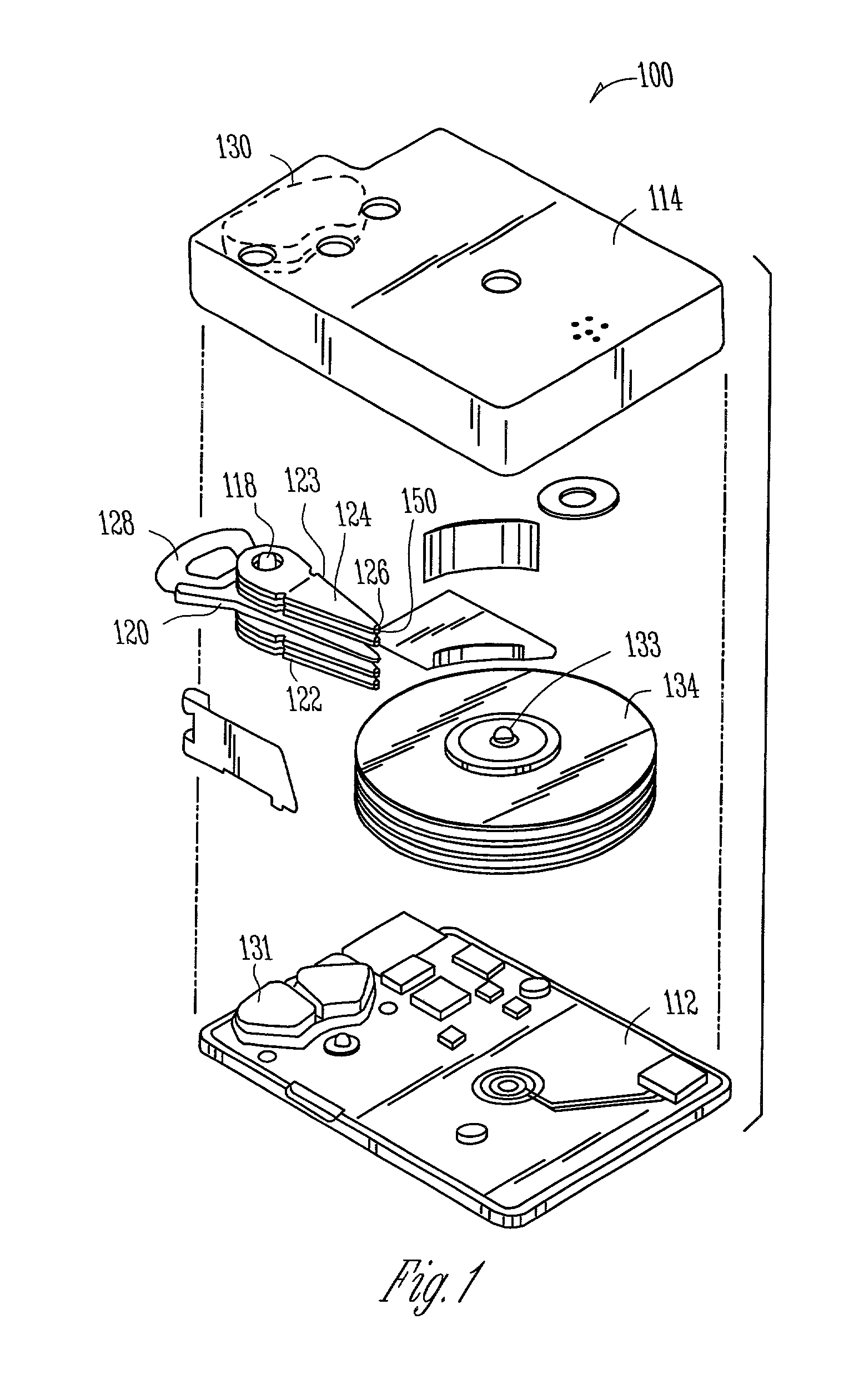
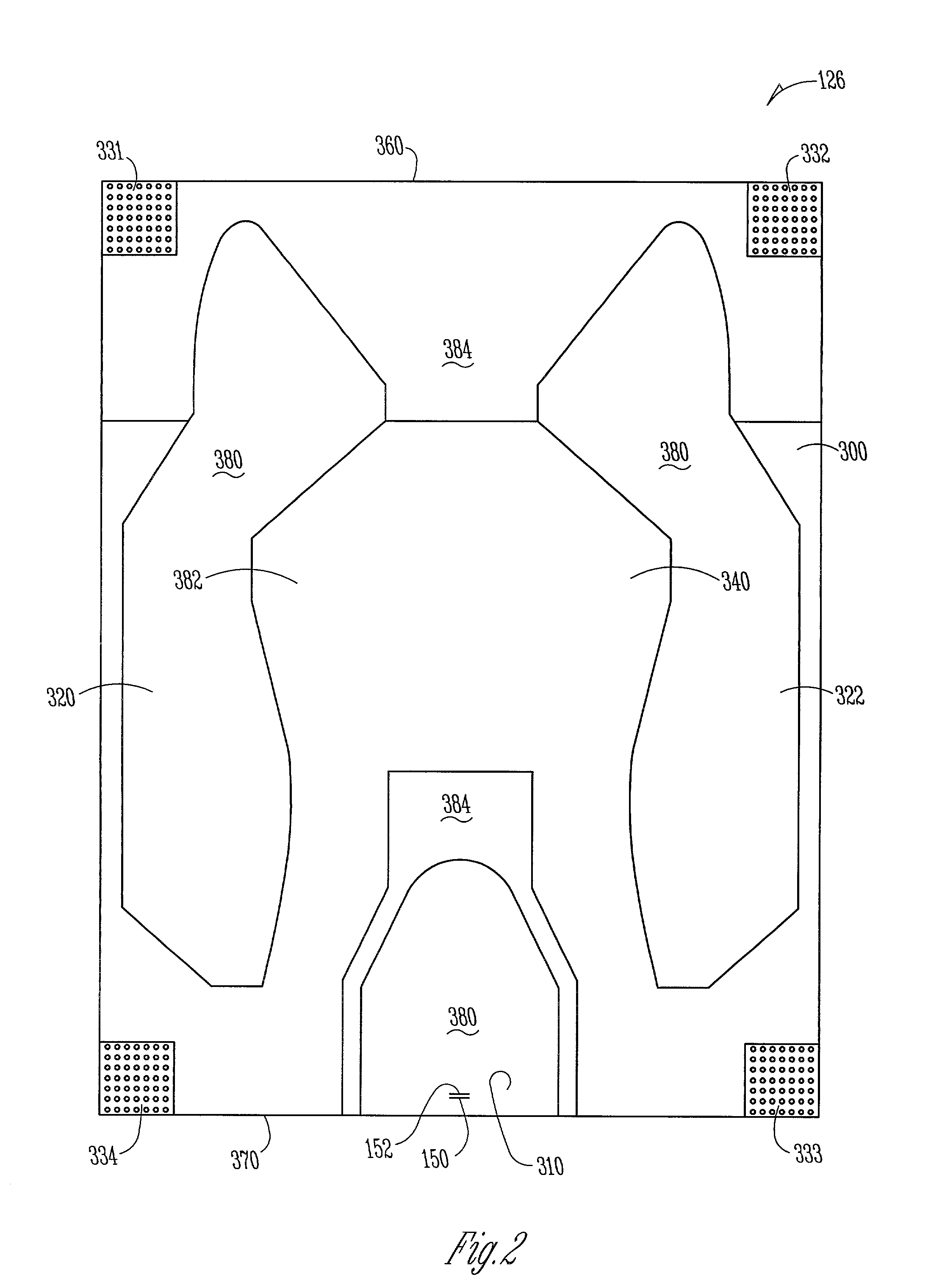
[0032]The invention described in this application is useful in any semiconductor fabrication process where it may be advantageous to control the process while it is occurring. One such process is during the removal of material from a bar of sliders 126 that will be used in a disc drive 100. FIG. 1 is an exploded view of one type of disc drive 100. The disc drive 100 includes a housing or base 112, and a cover 114. The base 112 and cover 114 form a disc enclosure. Rotatably attached to the base 112 on an actuator shaft 118 is an actuator assembly 120. The actuator assembly 120 inc...


PUM

PropertyMeasurementUnit
Electrical resistanceaaaaaaaaaa
Widthaaaaaaaaaa
Dynamicaaaaaaaaaa

Abstract

A method for producing magneto resistive heads includes the steps of positioning at least two magneto resistive elements in spaced relation to one another and placing the at least two magneto resistive elements in an ion milling environment where material is removed nonselectively from items in the environment. A property of at least two of the plurality of magneto resistive elements is monitored. In response to monitoring, one of the at least two magneto resistive elements is dynamically covered to prevent additional removal of material from the covered magneto resistive element.

Description

RELATED APPLICATION[0001]This application claims the benefit of U.S. Provisional Application Ser. No. 60 / 225,348 filed Aug. 15, 2000 under 35 USC 119(e) and U.S. Provisional Application 60 / 241,217 filed Oct. 13, 2000.FIELD OF THE INVENTION[0002]The present invention relates to the field of mass storage devices. More particularly, this invention relates to magneto resistive (“MR”) heads used in a disc drive.BACKGROUND OF THE INVENTION[0003]Many disc drives today use a transducer formed of two elements. A first element is a thin film head that is used for writing information representative of data to the surface of the memory disc. A second element is a magneto resistive element or giant magneto resistive element (“MR element”) that is used to read information representative of data from the surface of the memory disc. The resistance of the MR element changes in the presence of a magnetic field so the MR element is used to sense transitions on the disc that have been previously writte...

Claims


Application Information

Patent Timeline
IPC IPC(8): C23C14/34H01L21/306G11B5/31G11B5/39
CPCG11B5/3163G11B5/3166G11B5/3173G11B5/3903
Inventor REJDA, EDWIN FRANKHOEHN, JOEL WILLIAMHAO, SHANLINSTOVER, LANCE EUGENELUSE, TODD ARTHURPETERSON, JAMES RICHARD
Owner SEAGATE TECH LLC
Learn More