Method of production of a colloidal silica concentrate

a technology of colloidal silica and concentrate, which is applied in the field of colloidal silica concentration methods, can solve the problems of affecting the effective utilization and energy recovery of energy, affecting affecting the efficiency of energy recovery, so as to improve the stability of colloidal silica, stabilize the colloidal silica, and inhibit the agglomeration

Active Publication Date: 2018-05-03
GEO40 LTD
View PDF2 Cites 0 Cited by
  • Summary
  • Abstract
  • Description
  • Claims
  • Application Information

AI Technical Summary

Benefits of technology

[0154]One particular advantage of the present invention is the unexpected ability to form colloidal silica with a relatively uniform particle size distribution. This aspect of the invention is important because it is desirable for commercial grade silica to have a relatively uniform distribution, i.e. be monodisperse. Particle size is typically measured by dynamic light scattering (DLS), where the colloidal particle sizes are measured in situ by light scattering techniques. Coherent laser light is directed into the solution and the scattering of the light when detected, either by transmission or reflection, gives a measure of the particle size.
[0155]Preferably the method of producing a colloidal silica concentrate comprises a step of adding a dispersant to the geothermal fluid following colloidal silica formation and prior to being received at the first ultrafiltration unit. The inventors have found that the addition of a dispersant at this stage, in conjunction with controlling the temperature drop of the geothermal fluid via the heat exchanger, allows a particular colloid size and dispersity to be achieved and maintained. The dispersant is believed to substantially stop colloid formation thus arresting the increase in particle size dispersity that would otherwise occur. The dispersant also stabilises the colloids by inhibiting agglomeration to form gels which can foul equipment. Without wishing to be bound by theory, it is believed that the increased stability of the colloids is due to an increase in surface negative charge density which repels colloid particles from each other thus inhibiting agglomeration.
[0156]Dispersants will be known to those of skill in the art, however by way of example, the dispersant is selected from the group consisting of Nalco 980 and Accumer 5000. Preferably, the colloidal silica concentrate comprises a substantially monodisperse colloidal silica concentrate. Preferably, substantially monodisperse means that the standard deviation of the particle sizes of the colloidal silica is less than 50 nm. In some embodiments, the dispersity of the product is particularly important and the methods of the invention provide a substantially monodisperse product where the standard deviation of the particle sizes of the colloidal silica is less than 20 nm. The decreased standard deviation can be achieved by carefully maintaining the temperature during the settling and optionally the curing process. Preferably, the dispersant is added at a dosage of 5 ppm. Preferably, the dispersant added is between 1 and 10 ppm.
[0160]c. filtering the fluid to yield a concentrate of from 2 m % to 10 m % using ultrafiltration with a spiral wound membrane.
[0161]Preferably the colloidal silica concentrate is substantially monodisperse. Preferably, substantially monodisperse means the substantially monodisperse concentrate comprises a standard deviation of range of particles sizes of the colloidal silica of less than 50 nm.
[0162]Preferably, a dispersant is added after the growth period to substantially stop the colloid growth. Preferably, the method further comprises curing the fluid for a period following colloid formation and prior to the fluid being received at the first ultrafiltration unit. Preferably, the curing is carried out in one or more curing tanks. Preferably, a dispersant is added to the fluid prior to entering the curing tank and the period is sufficient for colloidal growth to substantially stop.

Problems solved by technology

However, if too much heat is extracted, the dissolved species will precipitate out of solution leading to scaling and fouling of pipes, watercourses and other equipment.
In addition, where geothermal fluids are re-injected into the ground, precipitation of species around the re-injection site can result in underground blockages and reduction in flow.
However, the precipitation problem is a major limitation preventing effective utilisation and energy recovery from geothermal sources.

Method used


Image

  • Method of production of a colloidal silica concentrate
  • Method of production of a colloidal silica concentrate
  • Method of production of a colloidal silica concentrate

Examples


example 1

ation at Nucleation Temperature

[0219]The polymerisation characteristics of a sample of geothermal fluid with predominantly dissolved monomeric silica was tested to determine colloid formation.

Materials and Methods

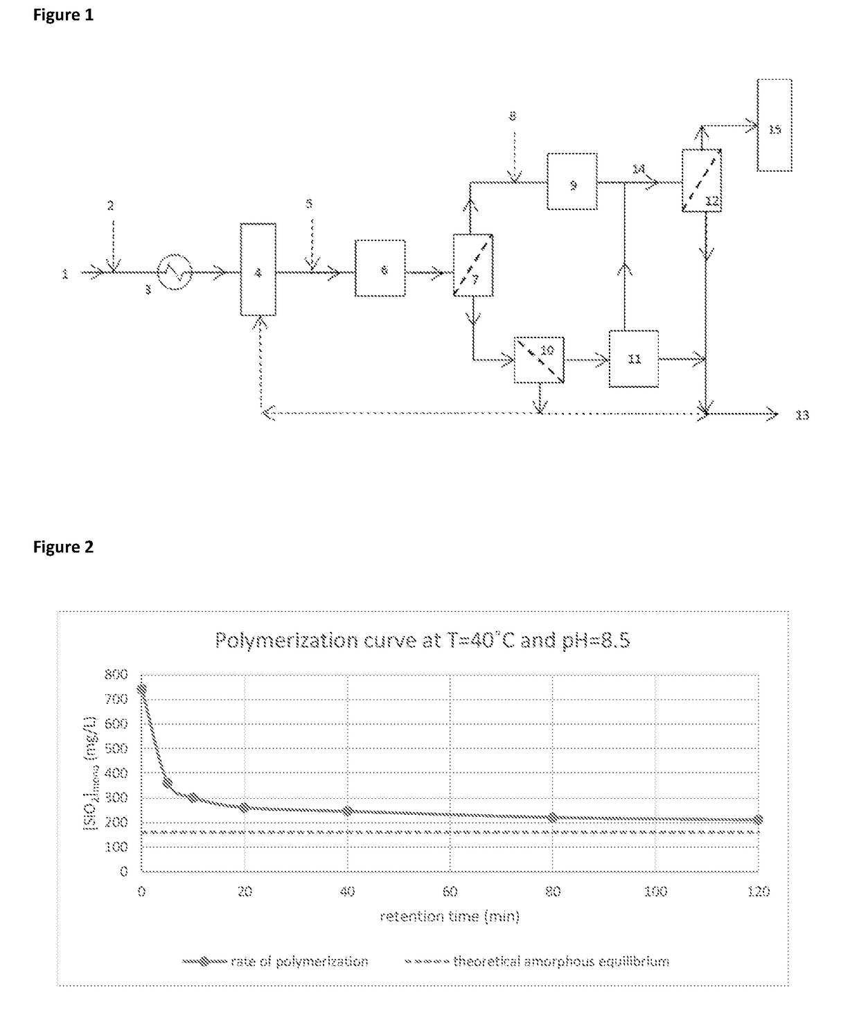
[0220]A sample of geothermal fluid from Wairakei (New Zealand) was taken and the monomeric silica concentration adjusted to approximately 740 ppm. The pH of the fluid was adjusted to approximately pH8.5 by addition of sodium hydroxide. The temperature of the fluid was maintained at approximately 40° C. by insulation of the sample in a thermos flask. The polymerisation characteristics of the sample were measured periodically using the molybdite method for molybdate reactive silica.

Results and Analysis

[0221]FIG. 2 shows the polymerisation curve at 40° C. and pH8.5. It can be seen that the greatest drop in monomeric silica concentration is within the first 20 minutes of the reaction. This indicates that the majority of colloidal silica will be formed during this time.

example 2

f Colloid Size and Dispersity

Materials and Methods

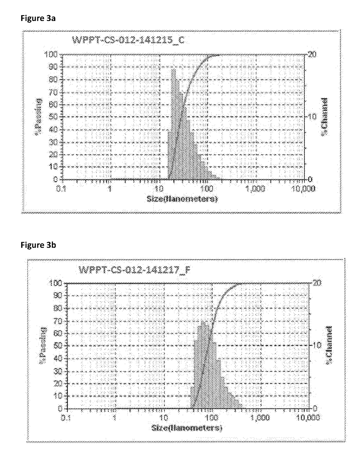
[0222]Samples of geothermal fluid were taken from the first UF concentrate at approximately 10 m % colloidal silica. Sample C was formed using fluid reduced to 40° C. and sample F was formed using fluid reduced to 70° C.

[0223]The mean number diameter (MN) was measured using dynamic light scattering (DLS). The calculated specific surface area (CS) and the standard deviation of the particle size (SD) were calculated. MN is the average particle size is weighted towards the number distribution. Therefore this average can be skewed by many small particles to drive the average size downward. This type of average is related to the population.

[0224]SA provides an indication of the specific surface area. This computation assumes smooth, solid, spherical particles.

[0225]SD is a function of the width of the measured particle size distribution. A larger standard deviation suggests a greater spread in the size range of particles.

Results

[0226]

TABL...

example 3

n of a Colloidal Silica Concentrate

Materials and Methods

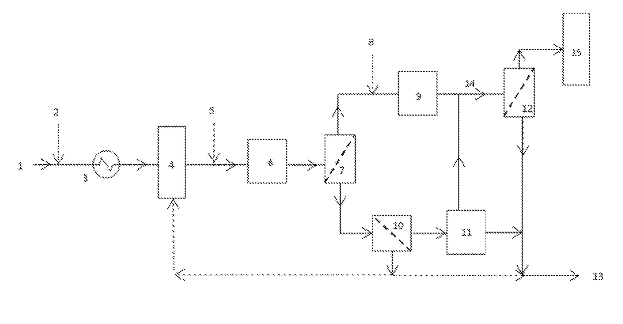
[0231]Separated geothermal water (SGW) was introduced into a system as shown in FIG. 1. The fluid was received at a series of plate heat exchangers which reduced the temperature from 126° C. to either 40° C. or 70° C. Caustic soda is also dosed prior to the heat exchangers to increase the pH to 8.5, which increases the rate of silica polymerisation. The fluid was then passed to five settling tanks with the fluid being retained in each one for seven minutes giving a total settling time of 35 minutes. This residence time allowed time for the colloids to form. The fluid is then dosed with a dispersant prior to entering the curing tank. The curing tanks will have a residence time of approximately two hours. The purpose of the dispersant is to charge the outer shell of the silica colloids with a negative charge which will cause individual silica particles to repel each other, thus resulting in a highly stable suspension. This preven...


PUM

PropertyMeasurementUnit
particles sizesaaaaaaaaaa
temperatureaaaaaaaaaa

Abstract

The invention relates to methods of concentration of colloidal silica in geothermal fluids. More particularly, although not exclusively, the invention relates to methods and apparatus for concentrating silica by ultrafiltration to produce a substantially monodisperse colloidal silica concentrate.

Description

FIELD OF INVENTION[0001]The invention relates to methods of concentration of colloidal silica in high temperature geothermal fluidsBACKGROUND[0002]Geothermally heated fluid has historically been used for direct heating but has more recently been harnessed to produce electricity. Electricity generated through geothermal power stations has been shown to be reliable, sustainable and environmentally friendly. Since geothermal power requires no fuel (except for running pumps in some power stations) it is insulated from fossil fuel cost fluctuations and dependencies. Geothermal power production also has significantly lower emissions of greenhouse gases when compared to fossil fuel electricity production methods and therefore has the potential to help mitigate global warming if widely deployed in place of fossil fuels.[0003]One major advantage over other renewable energy sources such as wind or solar is that geothermal power does not suffer from the intermittent supply inherent in these me...

Claims


Application Information

Patent Timeline
Patent Type & Authority Applications(United States)
IPC IPC(8): C01B33/14B01D61/14B01D61/16B01D61/58B01D61/02B01D63/12B01D63/06
CPCC01B33/14B01D61/142B01D61/16B01D61/58B01D61/025B01D63/12B01D63/06B01D2311/04B01D2311/106B01D2311/12B01D2311/2642B01D2315/16B01D2317/025B01D2317/022B01D61/146
Inventor MITCHELMORE, ANDREW W.O'SULLIVAN, MICHAEL T.
Owner GEO40 LTD
Why Eureka
Try Eureka