
Projector

Active Publication Date: 2020-06-25
SEIKO EPSON CORP
View PDF0 Cites 11 Cited by
  • Summary
  • Abstract
  • Description
  • Claims
  • Application Information

AI Technical Summary

Benefits of technology

The present patent relates to a new projector design that includes a special light source, a wavelength converter, a collimator system, a light separator, a correction lens, a superimposing lens, and a light modulator with pixels that produce different colors of light. The projector uses a microlens array to focus the light onto the pixel sub-pixels. The technical effects of the design include improved color accuracy and color separated projectors.

Problems solved by technology

However, the projector described above, in which the RGB light fluxes separated by the dichroic mirrors have optical path lengths different from one another, has a problem of a decrease in light use efficiency because the sizes of the areas illuminated with the color light fluxes differ from one another.

Method used


Image

  • Projector
  • Projector
  • Projector

Examples


first embodiment

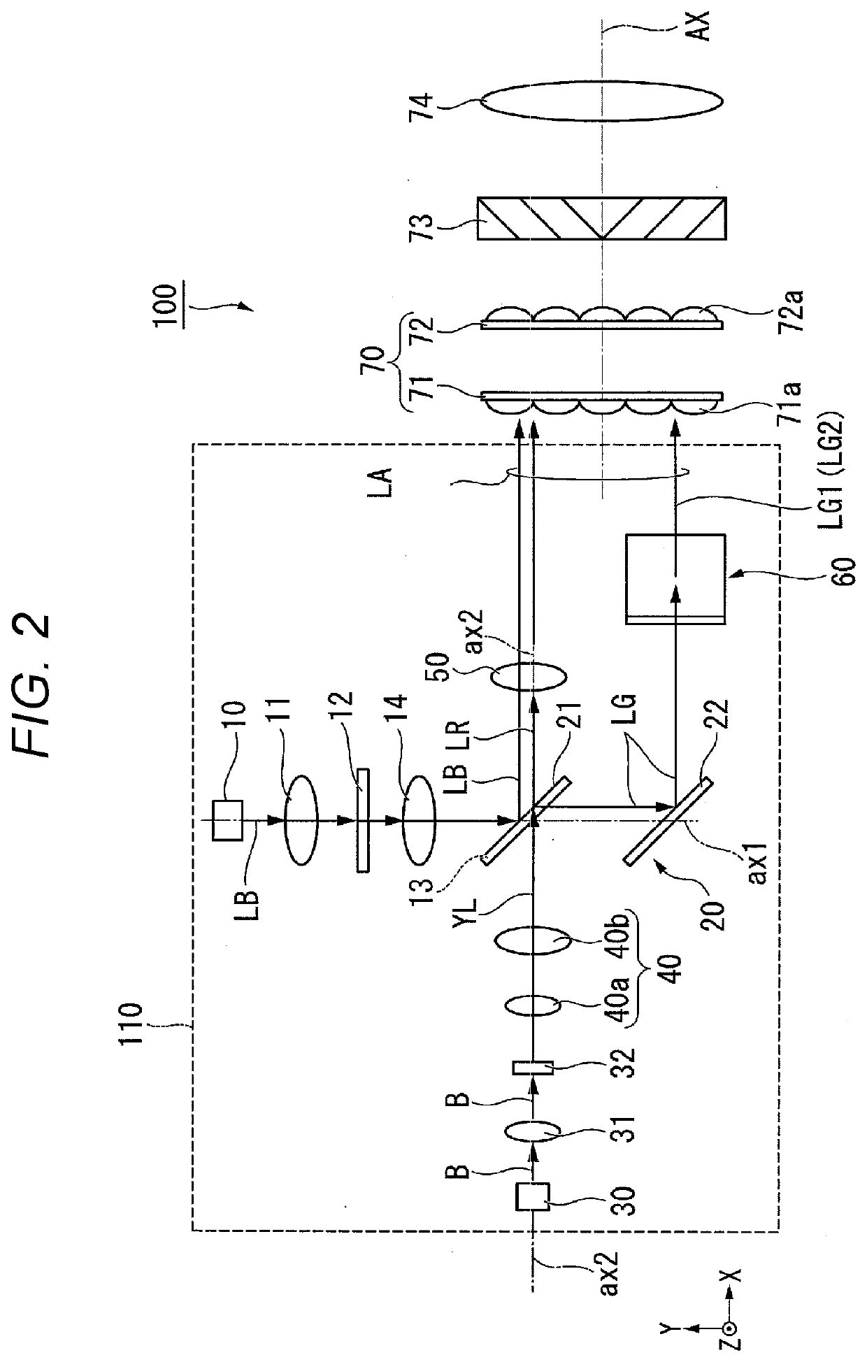
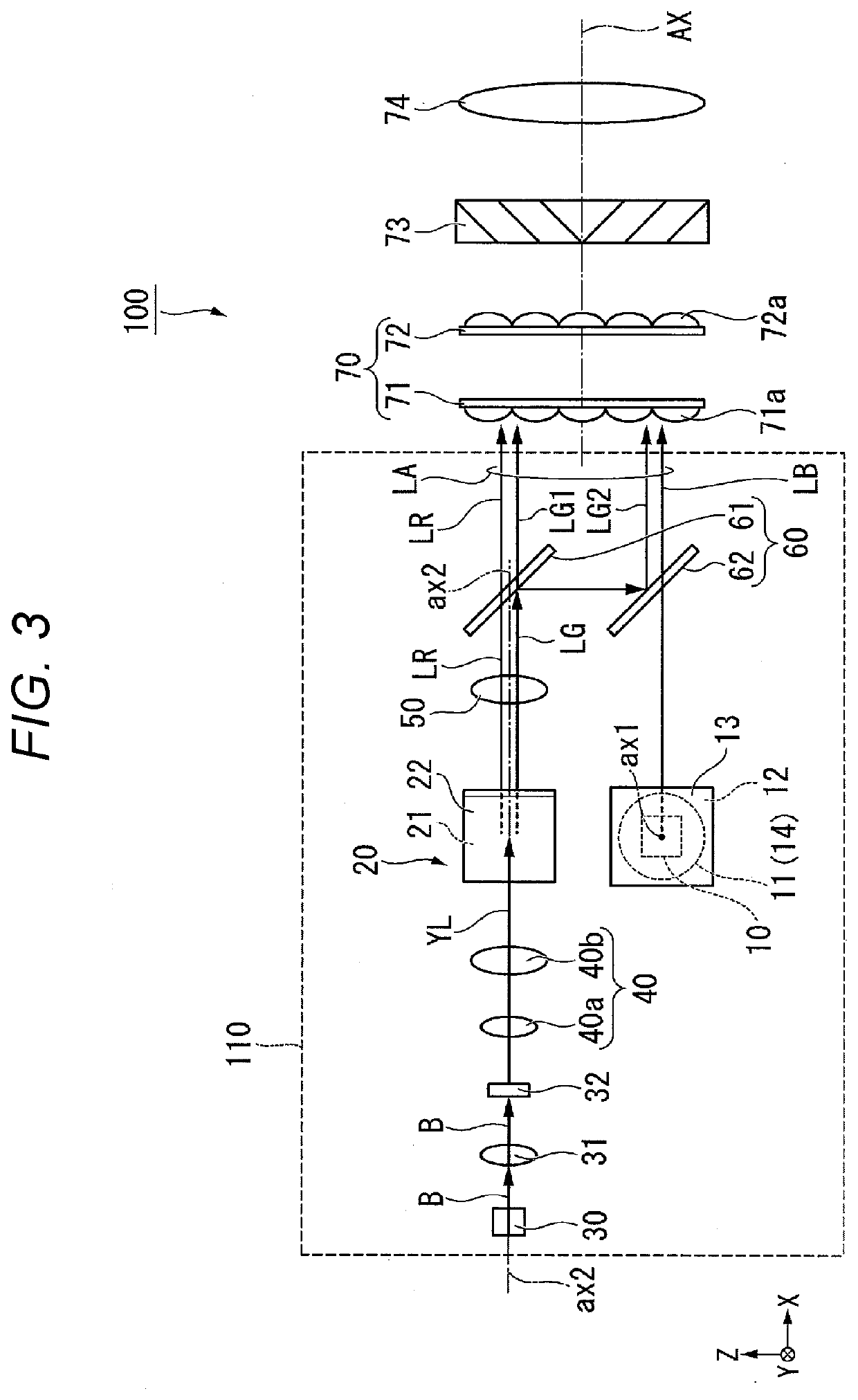
[0022]A projector according to the present embodiment is a projection-type image display apparatus that displays a color image on a screen. The projector according to the present embodiment uses a laser light source that produces high-luminance, high-power light, such as a semiconductor laser, as a light source of an illuminator.

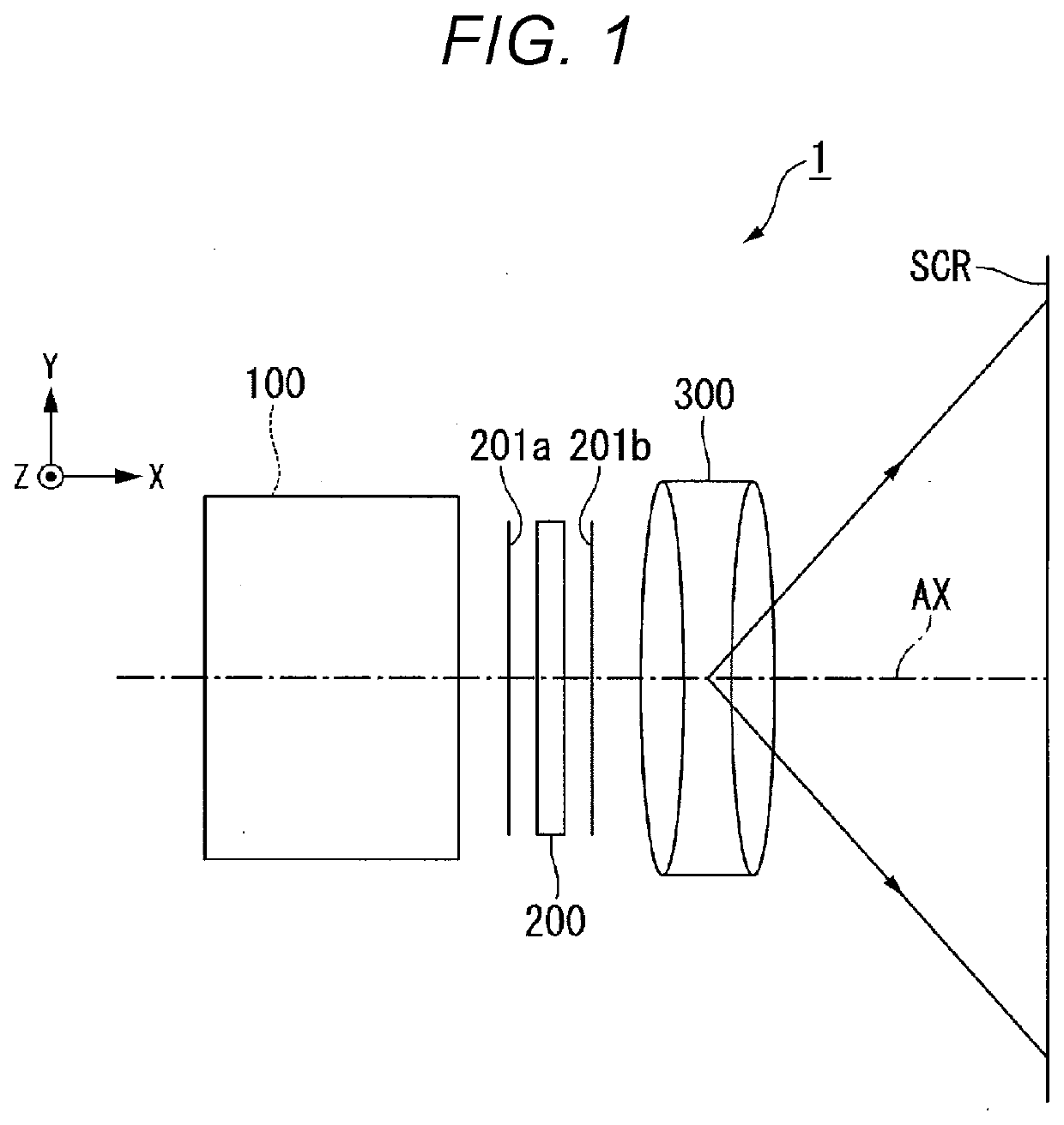
[0023]FIG. 1 is a plan view showing a schematic configuration of the projector according to the present embodiment.

[0024]A projector 1 includes an illuminator 100, a light modulator 200, and a projection optical apparatus 300, as shown in FIG. 1. In the projector 1, an illumination optical axis of illumination light outputted from the illuminator 100 is called an optical axis AX. An XYZ orthogonal coordinate system is used in the following description as required. The direction Z corresponds to the upward / downward direction of the projector, the direction X corresponds to the direction parallel to the optical axis AX, and the direction Y corresponds to the d...

second embodiment

[0079]The configuration of a projector according to a second embodiment will subsequently be described. The present embodiment differs from the first embodiment in terms of the position of the correction lens in the illuminator, and the other configuration is the same in the two embodiments. The following description will be primarily made of where the correction lens is disposed and the effect provided by the thus disposed correction lens. The same members and configurations as those in the first embodiment have the same reference characters and will not be described in detail.

[0080]FIG. 9 is a top view of an illuminator in the present embodiment. In FIG. 9, an illuminator 101 is viewed from the side facing the positive side of the direction Z toward the negative side of the direction Z. The illuminator 101 in the present embodiment includes a light source unit 111, the lens integrator unit 70, the polarization converter 73, and the superimposing lens 74, as shown in FIG. 9.

[0081]T...


PUM


Abstract

A present disclosure relates to a projector including a light source, an excitation light source, a wavelength converter, a collimator system that parallelizes fluorescence outputted from the wavelength converter, a light separator that separates the fluorescence into second light and third light, a correction lens provided in an optical path of the second or third light, a superimposing lens, a light modulator having a plurality of pixels each including first, second, and third sub-pixels, a microlens array including a plurality of microlenses corresponding to the plurality of pixels, and a projection optical apparatus. First light is incident on a first position on the superimposing lens, the second light is incident on a second position on the superimposing lens, the third light is incident on a third position on the superimposing lens The first light passes through the microlenses and is incident on the first sub-pixels. The second light passes through the microlenses and is incident on the second sub-pixels. The third light passes through the microlenses and is incident on the third sub-pixels.

Description

[0001]The present application is based on, and claims priority from JP Application Serial Number 2018-240277, filed Dec. 21, 2018, the disclosure of which is hereby incorporated by reference herein in its entirety.BACKGROUND1. Technical Field[0002]The present disclosure relates to a projector.2. Related Art[0003]There is a projector of related art that uses three dichroic mirrors disposed at different angles to separate white light from a light source into RGB light fluxes and causes the separated RGB light fluxes to be incident on one light modulator for image light generation (see JP-A-04-60538, for example).[0004]However, the projector described above, in which the RGB light fluxes separated by the dichroic mirrors have optical path lengths different from one another, has a problem of a decrease in light use efficiency because the sizes of the areas illuminated with the color light fluxes differ from one another.SUMMARY[0005]According to a first aspect of the present disclosure, ...

Claims


Application Information

Patent Timeline
IPC IPC(8): G03B21/20G02B3/00H04N9/31
CPCG02B3/0037G03B21/204H04N9/3108H04N9/3105H04N9/3152H04N9/3158H04N9/3164G02B3/0062G02B3/0056G03B21/208G03B21/005G03B21/2073
Inventor AKIYAMA, KOICHI
Owner SEIKO EPSON CORP
Learn More