
Heated conduit for delivering gas to a patient

Active Publication Date: 2020-07-02
KONINKLJIJKE PHILIPS NV
View PDF0 Cites 3 Cited by
  • Summary
  • Abstract
  • Description
  • Claims
  • Application Information

AI Technical Summary

Benefits of technology

The present invention provides a solution for improving the flexibility and comfort of respiratory devices by changing the heated wire breathing circuit from a 3-wire or 4-wire format to a 2-wire format. This change simplifies manufacturing, reduces cost, and simplifies the connection between the respiratory device and the patient. However, the 2-wire format poses technical challenges in providing both heating and temperature measurement functions. The patent proposes a closed loop temperature control system that addresses these challenges by utilizing a single thermistor wire and identifying the type of tube used. This solution allows for better patient comfort and improved respiratory device performance.

Problems solved by technology

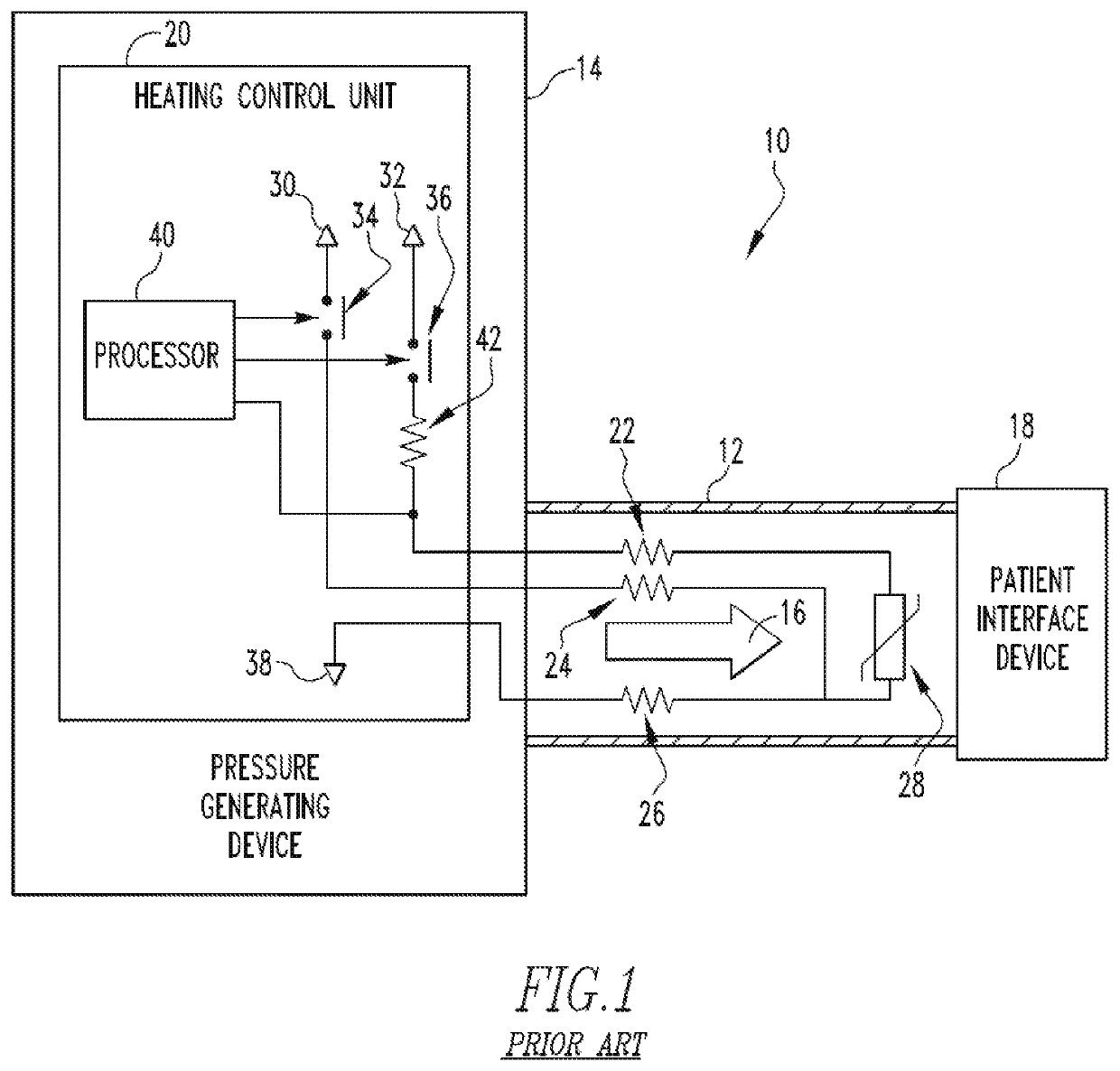
But there are technical challenges in providing both the heating function and proximal patient temperature measuring function when only 2 wires are utilized in said circuit.

Method used


Image

  • Heated conduit for delivering gas to a patient
  • Heated conduit for delivering gas to a patient
  • Heated conduit for delivering gas to a patient

Examples


Embodiment Construction

[0029]As used herein, the singular form of “a”, “an”, and “the” include plural references unless the context clearly dictates otherwise. As used herein, the statement that two or more parts or components are “coupled” shall mean that the parts are joined or operate together either directly or indirectly, i.e., through one or more intermediate parts or components, so long as a link occurs. As used herein, “directly coupled” means that two elements are directly in contact with each other. As used herein, “fixedly coupled” or “fixed” means that two components are coupled so as to move as one while maintaining a constant orientation relative to each other.

[0030]As used herein, the word “unitary” means a component is created as a single piece or unit. That is, a component that includes pieces that are created separately and then coupled together as a unit is not a “unitary” component or body. As used herein, the statement that two or more parts or components “engage” one another shall me...


PUM


Abstract

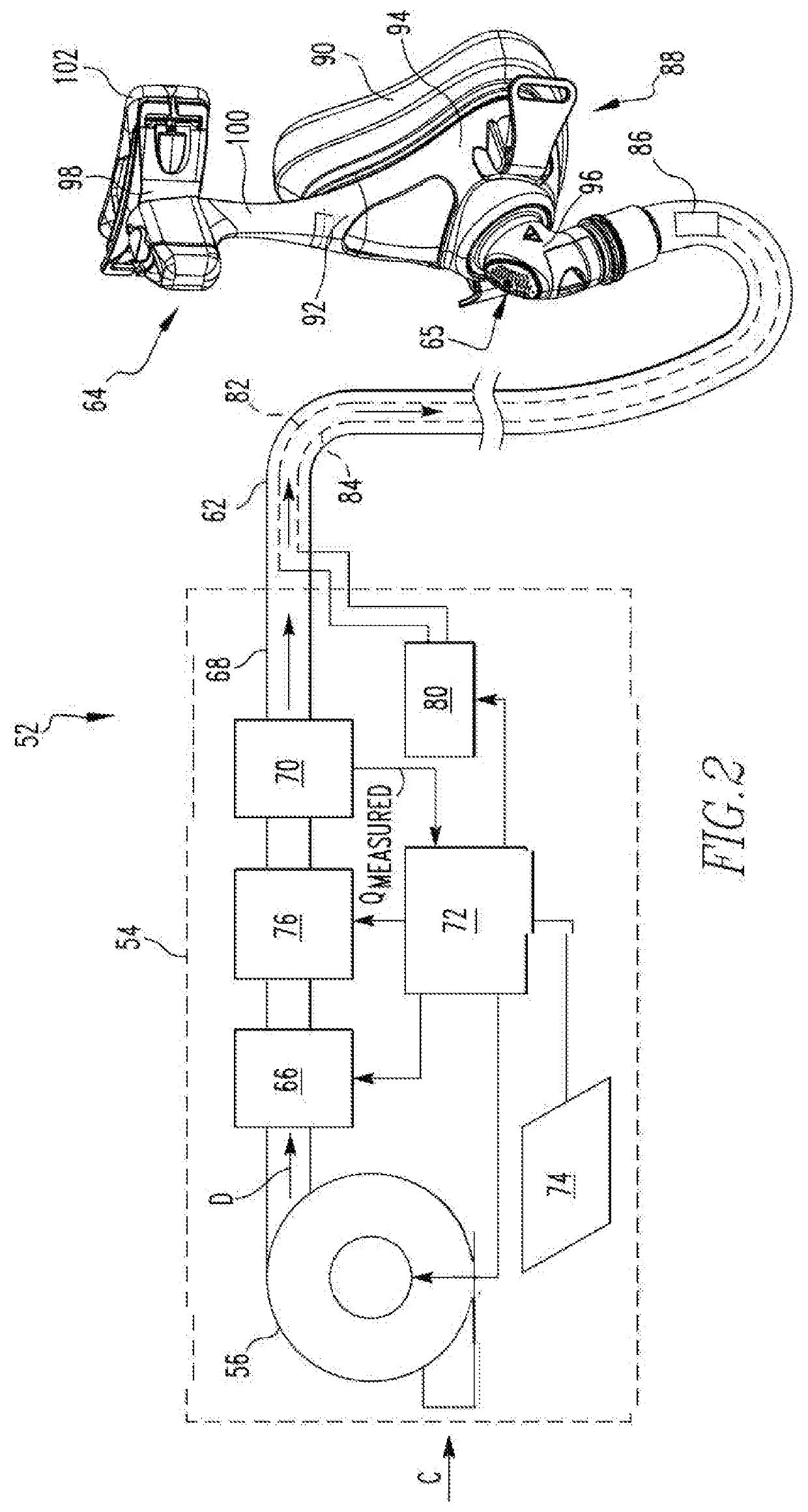
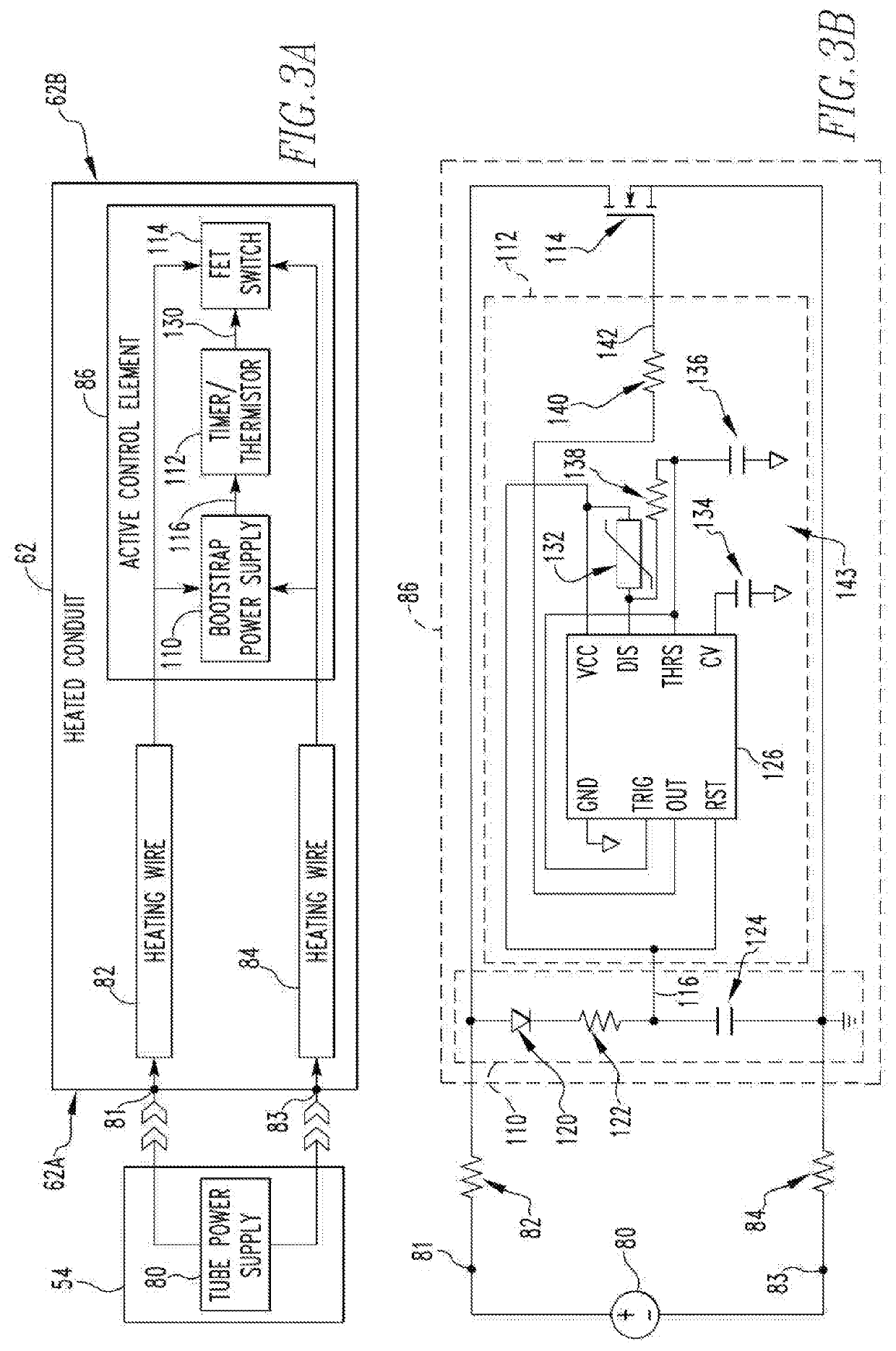
A conduit for communicating a flow of breathing gas from a pressure generating device to the airway of a patient. The conduit includes a first end which is structured to be coupled to the pressure generating device for receiving the flow of breathing gas and an opposite second end which is structured to be coupled to a patient interface device. The conduit further includes an active control element positioned at or near the second end; a first heating wire connected between the active control element and a first connection terminal positioned at or about the first end; and a second heating wire connected between the active control element and a second connection terminal positioned at or about the first end. Each of the first and second connection terminals are structured to be connected to a tube power supply.

Description

CROSS-REFERENCE TO RELATED APPLICATIONS[0001]This patent application claims the priority benefit under 35 U.S.C. § 119(e) of U.S. Provisional Application Nos. 62 / 784,565 and 62 / 787,556, filed on Dec. 24, 2018 and Jan. 2, 2019, respectively, the contents of each of which are herein incorporated by reference.BACKGROUND OF THE INVENTION1. Field of the Invention[0002]The present invention relates to heated conduits for communicating a flow of breathing gas from a pressure generating device to the airway of a patient. The present invention also relates to airway pressure support systems including heated conduits for delivering a flow of breathing gas to an airway of a patient.2. Description of the Related Art[0003]Many individuals suffer from disordered breathing during sleep. Sleep apnea is a common example of such sleep disordered breathing suffered by millions of people throughout the world. One type of sleep apnea is obstructive sleep apnea (OSA), which is a condition in which sleep ...

Claims


Application Information

Patent Timeline
IPC IPC(8): A61M16/00A61M16/06
CPCA61M16/0616A61M2016/0039A61M2016/0024A61M16/022A61M2205/3673A61M16/1095A61M16/0875A61M2205/3368A61M2205/50A61M16/0066A61M16/0633A61M2016/0036A61M16/16
Inventor KNEPPER, MICHAEL BJACOB, LAWRENCE ANTHONY
Owner KONINKLJIJKE PHILIPS NV
Features
  • Generate Ideas
  • Intellectual Property
  • Life Sciences
  • Materials
  • Tech Scout
  • Unparalleled Data Quality
  • Higher Quality Content
  • 60% Fewer Hallucinations
Learn More