
Terminal Approach Angle Guidance for Unpowered Vehicles

a technology of unpowered vehicles and approach angles, applied in direction controllers, weapons, transportation and packaging, etc., can solve the problems affecting the accuracy of the vehicle, and the algorithm cannot achieve the desired flight path angle, so as to achieve the effect of increasing the cost and size of the vehicl

Inactive Publication Date: 2020-07-09
CHARLES STARK DRAPER LABORATORY
View PDF0 Cites 1 Cited by
  • Summary
  • Abstract
  • Description
  • Claims
  • Application Information

AI Technical Summary

Benefits of technology

The patent describes a new method for guiding and controlling unpowered projectiles, such as sensor delivery systems, that can reach a target with a desired impact angle. The method uses a two-dimensional surface equation to calculate the optimal distance for the vehicle to start traveling downwards to the target while conserving energy. This approach allows for simpler and less expensive vehicles to be guided and controlled with low computational resources. The invention is a more efficient and cost-effective solution for guiding and controlling unpowered vehicles, reducing the size, complexity, and cost of the system.

Problems solved by technology

However, since such methods assume powered flight, the algorithms struggle to also achieve the desired flight path angle at impact.
This is more or less valid for a powered flight missile, but is much less valid for unpowered projectiles, which fly arc-like trajectories due to drag and gravity effects.
This solution, however, increases the cost and size of the vehicle,
Another problem with the current guidance approaches is that they are relatively computationally intensive and / or add additional size, mass, complexity, and / or cost requirements on the vehicle.
As a result, the proposed vehicles tend to be relatively large and / or require relatively powerful onboard flight control computers or the vehicles must relay sensor data to a ground station or airplane, which can perform the computations required and then relay control instructions to the vehicles.
Larger vehicles sized / mass limit their applications (i.e. cannot be fired as mutation or a given rocket or a given airplay payload).
Additional costs of adding sensors and larger actuators increase per unit cost of vehicle.
Real-time winds, aerodynamic uncertainty, and other variables cause the vehicle's trajectory to be perturbed from the ideal.

Method used


Image

  • Terminal Approach Angle Guidance for Unpowered Vehicles
  • Terminal Approach Angle Guidance for Unpowered Vehicles
  • Terminal Approach Angle Guidance for Unpowered Vehicles

Examples


Embodiment Construction

[0027]The invention now will be described more fully hereinafter with reference to the accompanying drawings, in which illustrative embodiments of the invention are shown. This invention may, however, be embodied in many different forms and should not be construed as limited to the embodiments set forth herein; rather, these embodiments are provided so that this disclosure will be thorough and complete, and will fully convey the scope of the invention to those skilled in the art.

[0028]As used herein, the term “and / or” includes any and all combinations of one or more of the associated listed items. Further, the singular forms and the articles “a”, “an” and “the” are intended to include the plural forms as well, unless expressly stated otherwise. It will be further understood that the terms: includes, comprises, including and / or comprising, when used in this specification, specify the presence of stated features, integers, steps, operations, elements, and / or components, but do not pre...


PUM


Abstract

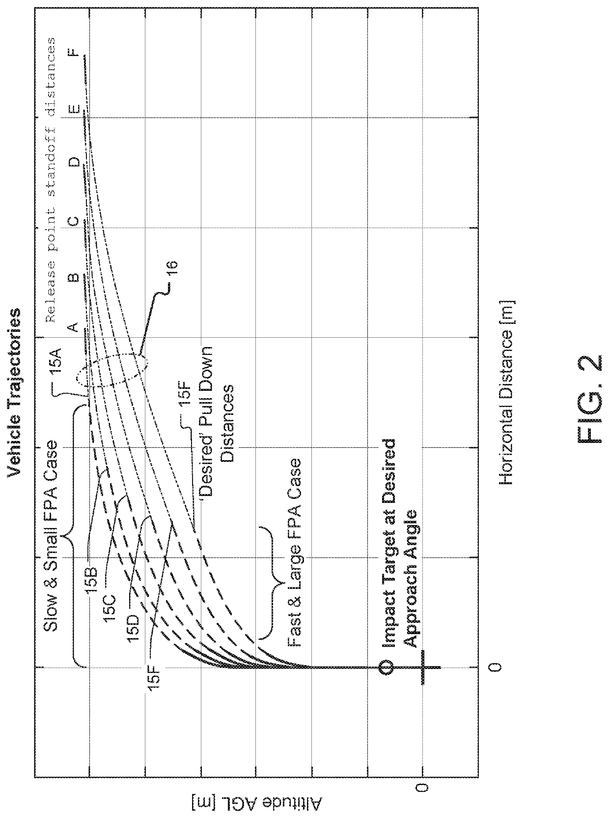
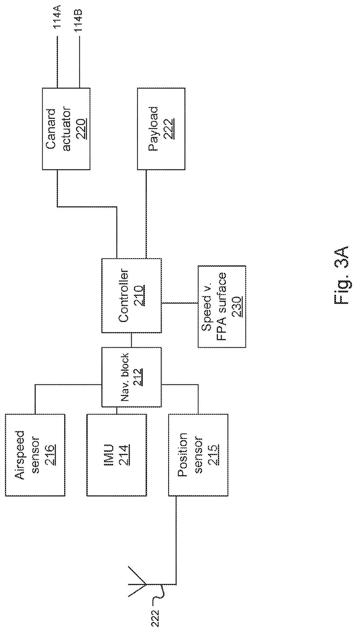
A ballistic descent vehicle comprises an airframe, one or more control surfaces for controlling a descent of the vehicle, a controller, and a sensor suite to estimate both relative position, velocity, and flight path angle. Such a controller guides the vehicle, via the control surfaces, based on the estimated vehicle states, and a preprogrammed equivalent airspeed versus flight path angle two dimensional surface. During flight, the controller periodically consults the pre-computed equivalent airspeed versus flight path angle surface to obtain a desired flight path angle such that the vehicle asymptotically approaches a desired terminal approach angle while successfully navigating to the target. The use of this preprogrammed surface allows for the control of such vehicles with significantly lower computational resources, smaller control surfaces, and / or without relative airflow sensors onboard.

Description

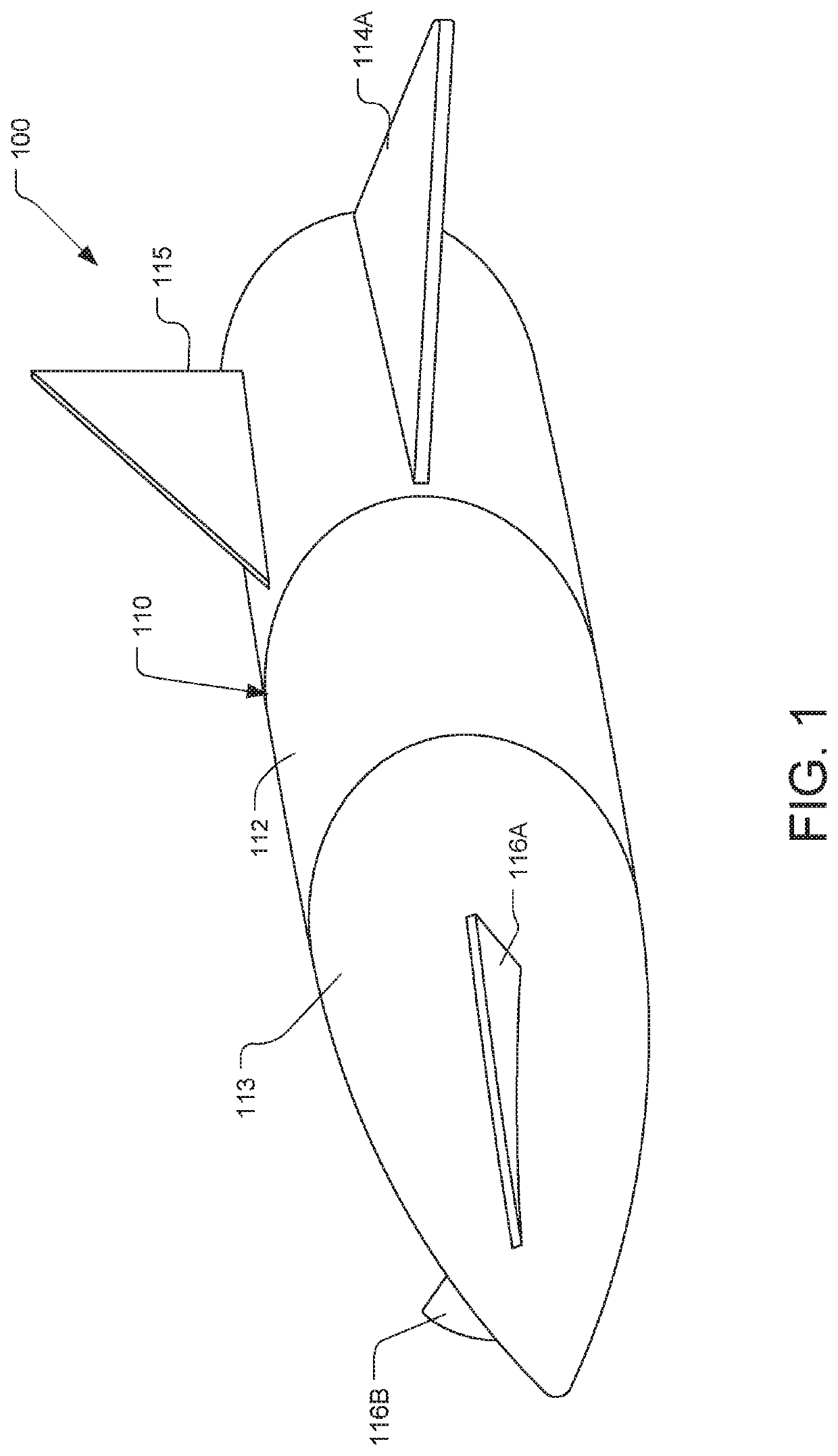
GOVERNMENT SUPPORT[0001]This invention was made with Government support under contract number Leidos HDTRA1-14-C-0019; Subcontract P010166674, awarded by the U.S. Department of Defense. The Government has certain rights in the invention.BACKGROUND OF THE INVENTION[0002]The term “ballistic descent vehicles” generally refers to vehicles that glide through the atmosphere. They can be dropped from a plane, or released from a slow moving aerial platform such as a drone. In some cases, they are launched from rockets or fired as projectiles.[0003]A number of applications, both military and commercial, require guidance of ballistic descent vehicles such that the vehicles reach desired targets with a desired terminal approach angle. In this application, the terminal approach angle is defined as the vehicle flight path angle prior to impact or landing. The vehicle could be a munition. On the other hand, there are other military, governmental, and commercial applications that could use such ve...

Claims


Application Information

Patent Timeline
IPC IPC(8): B64C13/16B64D7/00F42B10/64F42B10/02
CPCB64C13/16B64D7/00F42B10/64F42B10/02F41G7/346
Inventor SARGENT, RUSSELL E.STREETMAN, BRETT J.DUCHESNE, LAURENT
Owner CHARLES STARK DRAPER LABORATORY
Learn More