Compression tool for dental implantation sites, and a method of using the same

a compression tool and dental implant technology, applied in the field of tools, can solve the problems of reducing the heat generation reducing the efficiency of the entire borehole drilling process, so as to reduce the amount of heat generated

Inactive Publication Date: 2020-08-06
CARMEX PRECISION TOOLS
View PDF0 Cites 1 Cited by
  • Summary
  • Abstract
  • Description
  • Claims
  • Application Information

AI Technical Summary

Benefits of technology

[0012]The foregoing and other needs are satisfied by means of the new compression tool which comprises a shank or body portion defined around a longitudinally extending axis, and wherein the lower section of the shank or body portion comprises a plurality of longitudinally extending left-handed flute structures disposed around the external surface portion of the lower section of the shank or body portion within a circumferential array but wherein the plurality of flute structures are not spaced equiangularly around the longitudinal axis of the drill or osteotome. More particularly, it is seen that the plurality of flute structures may, for example, comprise six (6) flute structures, although the precise number of flute structures may vary, and that each flute structure comprises a right-hand leading crest or cutting edge portion, and trailing margin and relieved land portions. The margin portion is effectively disposed within the same tangential plane or circumferential locus as that of the leading crest or cutting edge portion, as considered in connection with the inner circumferential wall of the bone material defining the dental implantation site, while the relieved land portion is angled away from the tangential leading crest or cutting edge portion, and the margin portion, so as to effectively reduce the surface area disposed in contact with the inner circumferential wall of the bone material defining the dental implantation site which thereby, in turn, reduces the amount of heat generated during the compression or densification process of the procedure. The leading crest or cutting edge portion also leads into an arcuately configured groove or pocket section of each flute structure so as to effectively entrap and accumulate minute particles of bone which have been removed by means of the leading crest or cutting edge portions of the flute structures.
[0013]As a result of this integral composite flute structure, comprising the left-handed flutes with the right-handed cutting edges, as well as the margin, relieved, and grooved or pocket sections, the leading crest or cutting edge portions will therefore effectively remove minute particles of bone from the innermost circumferential wall surface of the bone surrounding the dental implantation site, such particles will then be effectively prevented from being evacuated from the implantation site so as to accumulate within the arcuately configured groove or pocket sections of the flute structures, and the margin portions will then compress such minute particles of bone radially outwardly and into the bone material circumferentially surrounding the implantation site, thereby enhancing the densification of such bone material circumferentially surrounding and defining the implantation site by means of compression and compaction. It is additionally noted that the lower fluted section of the shank or body portion is tapered a predetermined amount as one proceeds from the distal end, at which the flute structures begin, to the apical end, which is adapted to be inserted within a rotary motor or other power source so as to impart rotational movement to the compression tool, it being appreciated that the distal end of the compression tool is provided with the smallest diametrical extent. It is further noted, that in conjunction with such tapered fluted section, and the dimensions of the diametrical extents of the flute structures at any axial location along the longitudinally axial extent of the compression tool, that one side of the upper, non-fluted section of the shank or body portion has the diametrical extents, from smallest to largest, laser-marked upon an external surface portion of such upper, non-fluted section of the shank or body portion of the compression tool, while the diametrically opposite side of the upper, non-fluted section of the shank or body portion has the length of the fluted portion of the compression tool laser-marked upon its external surface portion. In this manner, the surgeon will know precisely which compression tool he will need or want to select in order to perform a particular finishing procedure in connection with the implantation site, both in terms of the length of the finished borehole to be formed within the implantation site, as well as the finished diametrical extent of the borehole formed within the implantation site.
[0014]In conjunction with such laser markings of the diametrical and length dimensions of the compression tool, the compression tool is also integrally provided with a circumferentially extending flanged portion at an axial location which separates the lower fluted section of the compression tool from the upper non-fluted section of the compression tool. This circumferentially extending flanged portion serves two purposes—the first purpose is that it effectively serves as a “physical barrier” or “stopper” whereby the dental practitioner knows that for the particular implantation site that he is operating on, further axial penetration of the compression tool into the implantation site is not to be pursued or else injury to the implantation site, or membranes or sinus regions within the jawbone or skull, may occur. The second purpose of the circumferentially extending flanged portion of the compression tool is that, in conjunction with the aforenoted laser markings indicating the taper of the compression tool, and the minimum and maximum diametrical extents of the lower fluted section of the compression tool, the circumferentially extending flanged portion is provided with two color-coded bands thereby further providing the dental practitioner with an additional visual indication of the fact that the compression tool is in fact tapered, and what the minimum and maximum diametrical extents of the compression tool are as are also noted upon the non-fluted shank portion of the compression tool. Lastly, it is also noted that, in conjunction with the “stopper” function of the circumferentially extending flanged portion of the compression tool, the distal end face of the compression tool is substantially flat so as to effectively ensure that the fluted end of the drill or osteotome cannot in fact pierce any membranes or enter any sinus cavities.

Problems solved by technology

However, there are several drawbacks to the system and method disclosed within these patents.
The use of such multiple drills or osteotomes renders the entire borehole drilling and finishing or burnishing process unnecessarily prolonged and tedious since the dental surgeon will need to periodically exchange several drills or osteotomes for other drills or osteotomes, having incrementally larger diametrical extents, until the drilled borehole has achieved the desired diametrical extent.
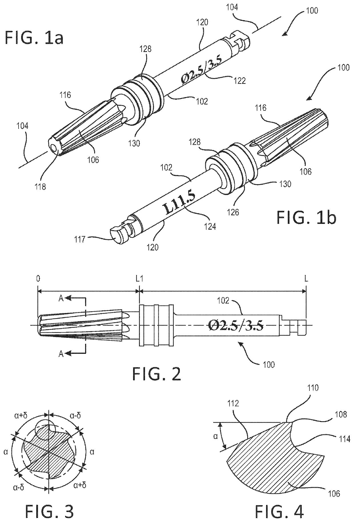
This equiangularly spaced, circumferential array of the flutes has been discovered to result in the chattering or vibration of the drill or osteotome as it undergoes its rotational movement.
It is known in the art that such monitoring techniques are conventionally employed by dental surgeons so as to ensure that the drill or osteotome has not reached depth levels beyond the intended depth level, which could be dangerous.
However, not only are such markings difficult to see during the actual drilling process, but in addition, such entails an obvious discontinuous procedural process of drilling, determining the depth to which the dental surgeon has drilled, continue drilling deeper, again determining the depth to which the dental surgeon has drilled further, and the like, thereby rendering the drilling process imprecise, tedious, and prolonged.
Again, however, this start, stop, and switch procedure is somewhat tedious and prolongs the formation of the desired osteotomy.
Still yet further, in accordance with the aforenoted manual, the drill or osteotome of Versah® is rotated at relatively high speeds comprising 800-1500 RPM, and requires constant water irrigation in order to prevent the implantation site from being subjected to significantly elevated temperatures, or else, such significantly elevated temperatures could potentially lead to the development of gangrene or other problems at the implantation site.
The problem with utilizing or needing continuous water irrigation, however, is that, in addition to being cumbersome while simultaneously drilling the borehole within the implantation site by means of the osteotome or drill, the use of irrigation water is in fact difficult to effectively achieve as a coolant within the lowermost depths of the drilled borehole where the vast majority of the heat is being generated as a result of the drilling process.
An additional operational drawback of the Versah® drill or osteotome is that when using the drill or osteotome, the dental practitioner needs to stop the drilling at various times in order to determine how far the drill or osteotome has drilled the borehole within the jawbone.
As has been noted hereinbefore, this type of operation can be somewhat tedious and time-consuming.
This structure, incorporated upon the distal end face of the drill or osteotome, can be potentially dangerous, however, in view of the fact that within the human skull, and more particularly within the human mandible or lower jawbone, or within the human maxilla or upper jawbone, various sinus cavities and / or membranes are present.
Improper or prolonged usage of the drill or osteotome, such as that illustrated within the aforenoted manual or Versah®, can potentially permit the sharply-pointed or conically configured distal end face of the drill or osteotome to easily pierce or penetrate such membranes and enter the sinuses with unwanted or undesirable deleterious effects such as, for example, within the upper jawbone or maxilla, such improper or prolonged usage of the drill or osteotome, with piercing of the membrane or intrusion into one of the sinus cavities can cause deafness.
In a similar manner, piercing of the membrane within the mandible or lower jaw can potentially lead to lockjaw.

Method used


Image

  • Compression tool for dental implantation sites, and a method of using the same

Examples


Embodiment Construction

[0021]With reference now being made to the drawings, and more particularly to FIGS. 1a-4, a new compression tool is disclosed and is generally indicated by the reference character 100. More particularly, it is seen that the new compression tool 100 comprises a shank or body portion 102 which is defined around a longitudinally extending axis 104, and wherein the lower section of the shank or body portion 102 comprises a plurality of longitudinally extending flute sections 106 disposed around the external surface portion of the lower section of the shank or body portion 102 within a circumferential array. It is to be noted that the plurality of flute sections 106 are not spaced equiangularly around the longitudinal axis 104 of the drill or osteotome 100 as can best be appreciated from FIG. 3, wherein it is clearly illustrated that the angular spacing defined between some adjacent flute sections is denoted by means of the angle cc, whereas the angular spacing defined between some other...


PUM


Abstract

A compression tool for performing a finishing procedure, within a bore hole formed within a human jawbone so as to serve as an implantation site for a dental implant, by compression and densification processes, comprises a tapered body portion, and a plurality of flute sections disposed the body portion, wherein, when the compression tool is rotated in a clockwise direction and simultaneously axially inserted into the bore hole, the plurality of flute sections, which comprise structure for continuously cutting bone material from bone mass surrounding and defining the bore hole formed within the human jawbone, for accumulating the bone material so as to prevent the bone material from being evacuated from the implantation site, and for immediately compressing the bone material, cut from the bone mass surrounding and defining the bore hole formed within the human jawbone, back into the bone mass surrounding and defining the bore hole formed within the human jawbone will compress, compact, and enhance the density of the bone mass surrounding and defining the bore hole formed within the human jawbone.

Description

FIELD OF THE INVENTION[0001]The present invention relates generally to tools, and more particularly to a new compression tool for use in connection with the enhancement of the thickness and density of the bone sections forming or surrounding a dental implantation site.BACKGROUND OF THE INVENTION[0002]Various medical drills or osteotomes are of course known in the art. Examples of some known drills or osteotomes can be appreciated from U.S. Pat. No. 10,039,621 which issued to Huwais on Aug. 7, 2018; U.S. Pat. No. 9,028,253 which issued to Huwais on May 12, 2015; and U.S. Pat. No. 9,022,783 which issued to Huwais on May 5, 2015. Still yet further, other drills or osteotomes are disclosed within the Versah® manual entitled Densah® Bur Surgical Technique Manual. As noted within the Huwais U.S. Pat. No. 9,022,783, there is disclosed an apparatus and method for enlarging an existing osteotomy by utilizing a plurality of drills or osteotomes having progressively larger diametrical extents ...

Claims


Application Information

Patent Timeline
Patent Type & Authority Applications(United States)
IPC IPC(8): A61C8/00A61B17/16A61B17/88
CPCA61B17/885A61B17/1615A61C8/0089A61B17/1604
Inventor JACOBY, OMERCOHEN, YUVAL
Owner CARMEX PRECISION TOOLS
Why Eureka
Try Eureka